7 . ACCESSORIES AND OPTIONS
7.78
Challenger MT500B EU
• Press the key «
6
. Calibration starts and a new window
is displayed (Fig. 187).
DANGER: Ensure that no one can enter the front link-
age operating area throughout the calibration process.
During calibration, the rear implement is lifted and lowered
several times. Then, as soon as calibration is complete, the
window (Fig. 184) is displayed again.
DANGER: Ensure that no one can enter the front link-
age operating area throughout the calibration process.
IMPORTANT: In an emergency, press the key
«
6
(STOP)
to stop calibration.
When sensor calibration is complete, a new window is dis-
played (Fig. 188). This indicates the values read by the DA-
TATRONIC required by the service engineer.
• To return to the SETTINGS window, press the ESC key.
7.13.3.2 - Downloading the calibration
If different implements are to be used, the rear implement
sensor calibration can be stored in different memories. This
avoids recalibrating the sensor.
IMPORTANT: However, if work is carried out on the rear
implement sensor, it will have to be recalibrated.
The downloading procedure is identical to that of the
FRONT DUAL CONTROL. See paragraph 7.8.2.2. (Down-
loading the calibration).
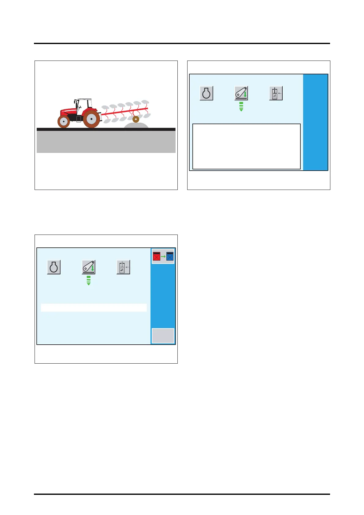
7.13.3.3 - Memorising high and low linkage positions
For REAR DUAL CONTROL operation, the DATATRONIC
must know the high and low positions of the linkage and
the plough depth wheel. It must therefore be entered with
these values.
Memorising the high position:
• Place the linkage and depth wheel in high position
(plough horizontal Fig. 189) using the following controls:
- the linkage control and high position limiter,
- the plough depth wheel spool valve control.
Z3A-1014-08-04
Fig. 186
1500
3<<..<<4
CALIBRATION EN COURS ...
CALIBRATION MODE
RPM
Sensor = 20
STOP
Z3A-1013-08-04-B
Fig. 187
1500
3<<..<<4
CALIBRATION MODE
RPM
A CB
1
6
238
165
47
44
OK ! ! PRESS ESC ! ! !
Z3A-1374-12-04
Fig. 188
 Loading...