EasyManua.ls Logo

Chamberlain 045DCT User Manual

Chamberlain 045DCT
12 pages
To Next Page IconTo Next Page
Page #1 background imageLoading...
Page #1 background image
1
Before you begin
1
Installation
RECEIVER LOGIC BOARD REPLACEMENT
Models 045DCT and 045DCT125
1.2 To maintain your warranty, place the
provided label over the existing label on
the end panel of the garage door opener.
.
.
1.1 Remove the light lens by pulling the top
sides of the light lens and rotate the light
lens down. Squeeze the light lens clips to
remove lens from end panel.
NOTE: The products illustrated in the instructions are for reference. Your product may look different.
1.3 Disconnect electrical and battery power
(if applicable) to the garage door opener.
Remove the receiver logic board
2
2.1 Disconnect the wires from the quick-connect terminals (A).
Remove the receiver logic board end panel from the garage
door opener.
2.2 Unplug the wire harnesses from the receiver logic
board. You may need needle-nosed pliers, to
remove the harnesses.
2.3 Remove the receiver
logic board from the
end panel by removing
the 2 screws and
releasing the 2 clips.
To prevent possible SERIOUS INJURY or
DEATH:
Disconnect ALL electric and battery
power BEFORE performing ANY service
or maintenance.
To prevent damage to the receiver/logic
board, DO NOT touch printed circuit board
of replacement receiver/logic board during
installation.
ALWAYS wear protective gloves and eye
protection when changing the battery or
working around the battery compartment.
Screws
Clips
A
To insert or remove
the wires from the
terminal, push in the
tab with a
screwdriver tip.
Red
White
White
Grey
Question and Answer IconNeed help?

Do you have a question about the Chamberlain 045DCT and is the answer not in the manual?

Chamberlain 045DCT Specifications

General IconGeneral
BrandChamberlain
Model045DCT
CategoryReceiver
LanguageEnglish

Summary

Installation

Before you begin

Safety precautions and initial setup steps before replacing the receiver/logic board.

Remove the receiver logic board

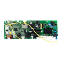
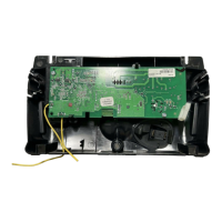
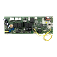
Steps to disconnect wires, unplug harnesses, and physically remove the old receiver logic board.

Install new receiver logic board

Instructions for connecting wire harnesses, antenna wires, and reassembling the new logic board.

Programming

Program a remote using the learn button

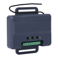
Procedure to pair a remote control with the garage door opener using the learn button.

Adjustment

Program the travel

Guide to setting the full open and close limits for the garage door.

Test the Safety Reversal System

Test the Safety Reversal System

Procedure to verify the garage door reverses upon contact with an obstruction.

Test the Protector System

Test the Protector System

Procedure to verify the garage door opener will not close if sensors are obstructed.

Related product manuals