EasyManua.ls Logo

Chamberlain 050DCTWF User Manual

Chamberlain 050DCTWF
12 pages
To Next Page IconTo Next Page
Page #1 background imageLoading...
Page #1 background image
1
Before you begin
1
Installation
RECEIVER LOGIC BOARD REPLACEMENT
Model 050DCTWF
1.2 To maintain your warranty, place the
provided label over the existing label on
the end panel of the garage door opener.
1.1 Remove the light lens by pulling the top
sides of the light lens and rotate the light
lens down. Squeeze the light lens clips to
remove lens from end panel.
1.3 Disconnect electrical and battery power
(if applicable) to the garage door opener.
Remove the receiver logic board
2
2.1 Disconnect the wires from the quick-connect terminals (A).
Remove the receiver logic board end panel from the garage
door opener.
2.2 Unplug the wire harnesses from the receiver logic
board. You may need needle-nosed pliers, to
remove the harnesses.
2.3 Remove the receiver
logic board from the
end panel by removing
the 2 screws and
releasing the 2 clips.
To prevent possible SERIOUS INJURY or
DEATH:
Disconnect ALL electric and battery
power BEFORE performing ANY service
or maintenance.
To prevent damage to the receiver/logic
board, DO NOT touch printed circuit board
of replacement receiver/logic board during
installation.
ALWAYS wear protective gloves and eye
protection when changing the battery or
working around the battery compartment.
Screws
Wire clip
Clips
A
To insert or remove
the wires from the
terminal, push in the
tab with a
screwdriver tip.
Red
White
White
Grey
Your garage door opener has an internal gateway located on the receiver logic board. After installing the new receiver logic board, use the MyQ
®
serial number found on the provided label to add your
garage door opener to your MyQ
®
account. The products illustrated in the instructions are for reference. Your product may look different.
WARNING: This product can expose you to chemicals including lead, which are known to the State of California to cause cancer or birth defects
or other reproductive harm. For more information go to www.P65Warnings.ca.gov
Question and Answer IconNeed help?

Do you have a question about the Chamberlain 050DCTWF and is the answer not in the manual?

Chamberlain 050DCTWF Specifications

General IconGeneral
SecurityRolling code technology
TypeWireless Receiver
ConnectivityWireless
Compatibilitygarage door openers
Power SourceHardwired to garage door opener

Summary

Garage Door Opener Installation and Programming

Installation: Before You Begin

General advice and warnings before starting the receiver logic board installation process.

Disconnect Power Sources

Critical safety step to disconnect all electric and battery power before performing any service.

Remove Receiver Logic Board

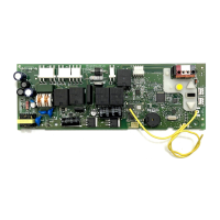
Step-by-step instructions for removing the existing receiver logic board.

Disconnect Wires and Harnesses

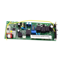
Instructions for disconnecting wires from terminals and unplugging wire harnesses.

Remove Logic Board from Panel

Instructions for removing the logic board by unscrewing and releasing clips.

Install New Receiver Logic Board

Connect Wire Harnesses

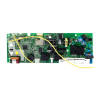
Guidance on connecting wire harnesses to the new receiver logic board correctly.

Mount New Logic Board

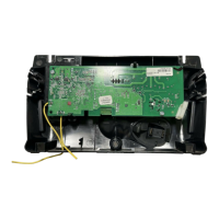
Steps for inserting antenna wires and mounting the new logic board onto the end panel.

Reconnect Wires

Instructions for reconnecting door control and safety sensor wires to terminals.

Install Light Lens

Steps for installing the light lens and reconnecting power after board replacement.

Program Remote Control

Initiate Programming Mode

Press and release the Learn button to activate programming mode.

Press Remote Button

Within 30 seconds, press and hold the button on the remote control.

Confirm Learning

Release remote button when opener light blinks, confirming the code is learned.

Adjust Garage Door Travel

Enter Travel Programming

Press and hold the Adjustment Button to begin programming the travel limits.

Set UP Travel Position

Press and hold the UP Button until the door reaches the desired UP position.

Confirm UP Position

Press and release the Adjustment Button to confirm the UP position.

Set DOWN Travel Position

Press and hold the DOWN Button until the door reaches the desired DOWN position.

Confirm DOWN Position

Press and release the Adjustment Button to confirm the DOWN position.

Test UP Travel

Press and release the UP Button to test the programmed UP travel.

Test DOWN Travel

Press and release the DOWN Button to test the programmed DOWN travel.

Safety System Testing

Test Safety Reversal System

Procedure to test the safety reversal system by using an obstruction.

Test Protector System

Procedure to test the safety reversing sensors by obstructing the beam.

Synchronize Door Control

Steps to synchronize the door control to the garage door opener.

Related product manuals