1
Before you begin
1
Installation
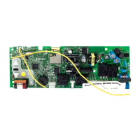
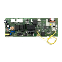
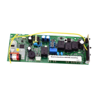
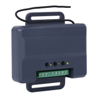
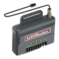
RECEIVER LOGIC BOARD REPLACEMENT
Models 050DCTBMC and 050DCTBLKMC
1.2 To maintain your warranty,
place the provided label
over the existing label
on the end panel of the
garage door opener.
1.1 Remove the light lens by pulling
the top side of the light lens
and swing the light lens down.
Squeeze the light lens clips to
remove lens from end panel.
1.3 Disconnect electrical and battery
power (if applicable) to the
garage door opener.
Remove the receiver logic board
2
2.1 Disconnect the wires from the quick-connect terminals
(A). Disconnect any wires from the lock terminals.
Remove the receiver logic board end panel from the
garage door opener.
2.2 Unplug the wire harnesses from the receiver logic
board. You may need needle-nosed pliers, to
remove the harnesses.
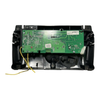
2.3 Remove the receiver
logic board from the
end panel by removing
the 2 screws and
releasing the 2 clips.
To prevent possible SERIOUS INJURY or DEATH:
• Disconnect ALL electric and battery power BEFORE performing ANY
service or maintenance.
Screws
Wire clip
Clips
A
To insert or remove the wires from the terminal,
push in the tab with a screwdriver tip.
Lock
Terminals
Red
White
White
Grey
Your garage door opener has an internal gateway located on the receiver logic board. After installing the new receiver logic board, use the myQ
®
serial number found on the provided label to add your
garage door opener to your myQ
®
account. The products illustrated in the instructions are for reference. Your product may look different. The logic board firmware has been updated. The update provides
a new Obstruction Notification that signals when the opener senses resistance, such as an obstruction or other binding in the door and rail system. The door will stop or reverse to open limit and the
opener will beep and the lights flash 5 times.
WARNING: This product can expose you to chemicals including
lead, which are known to the State of California to cause cancer or
birth defects or other reproductive harm. For more information go
to www.P65Warnings.ca.gov.
To prevent damage to the receiver/logic board, DO NOT touch printed
circuit board of replacement receiver/logic board during installation.
ALWAYS wear protective gloves and eye protection when changing the
battery or working around the battery compartment.
NOTE: 050DCTB replaces 050DCTWF and 050DCTBLK replaces 050DCTWFLK. 050DCTBMC replaces DCTB/DCTWF, and DCTBLKMC replaces DCTBLK and DCTWFLK.