Do you have a question about the Chamberlain 140 and is the answer not in the manual?
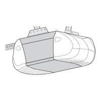
Describes automatic and manual operation of opener lights for safety and convenience.
Explains independent up/down force adjustment and automatic reversal/stopping features for safety.
Details how to manually operate the door using a pull cord disconnect.
Explains the automatic reconnection of the trolley after an emergency disconnect.
Notes the permanently lubricated motor with automatic reset for reliable operation.
Mentions that radio control codes can be easily changed by the owner.
Describes the simple screw-based adjustment of door opening and closing limits.
Explains how the lock switch prevents transmitter operation, allowing control via wall button or key accessories.
Lists motor type (split capacitor), speed (1500 rpm), voltage (120V AC), and current (4.5 amps).
Details gears (16:1 worm gear), drive (chain on tee-rail), travel length, travel rate, lamp, and door linkage.
Covers safety features like push button reversal, automatic stop, independent force adjustment, and overload protection.
Provides overall length (128 inches), headroom required (2 inches), and hanging weight (32 pounds).
Explains how limit settings regulate the door's stop points for opening and closing.
Outlines the steps to run the opener through a complete cycle for limit adjustments.
Provides guidance on adjusting UP/DOWN travel and closing issues based on specific door behaviors.
Locates force adjustment controls on the rear panel and explains their function.
Guides on adjusting DOWN (CLOSE) FORCE and UP (OPEN) FORCE based on door behavior.
Stresses the importance of the safety reverse test for preventing injury.
Details the process of testing the safety reverse system with a 1-inch floor obstruction.
Lists conditions requiring re-testing the safety reverse system after repairs or adjustments.
Describes the optional system for added safety against entrapment using an invisible beam.
Provides instructions for setting or changing the transmitter's code to match the receiver.
Outlines the procedure for synchronizing the receiver with the transmitter's smart code button.
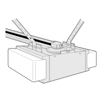
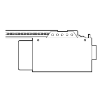
Lists and illustrates parts for the rail assembly, including master link, trolleys, and rail sections.
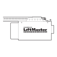
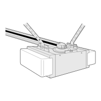
Identifies components used during initial installation, such as wall control and header bracket.
Shows the limit switch assembly with wires and contacts for controlling travel limits.
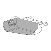
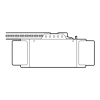
Lists various internal components of the opener chassis, including motor, gears, and logic boards.
Provides a toll-free number for installation and service support, available six days a week.
Specifies required details like part number, name, and model number for ordering parts.
Gives the mailing address for ordering parts from the Electronic Parts and Service Department.
Details specific motor warranty periods for different models (550/550-2M, 350).
Lists exclusions from the warranty, such as damage from abuse or unauthorized alterations.
Lists the 750CB as a substitute accessory for original model 50.
Lists the 753CB as a substitute accessory for original model 53.
Lists the 756CB as a substitute accessory for original model 54.
Lists 41A3685 as a substitute accessory for original model 54.
Lists 65LM as a substitute accessory for original model 65LM.
Lists 760CB as a substitute accessory for original model 60.
Lists 7702cb as a substitute accessory for original model 1702CB, used for manual operation during power failure.
| Brand | Chamberlain |
|---|---|
| Model | 140 |
| Category | Garage Door Opener |
| Language | English |