Factory
Setting
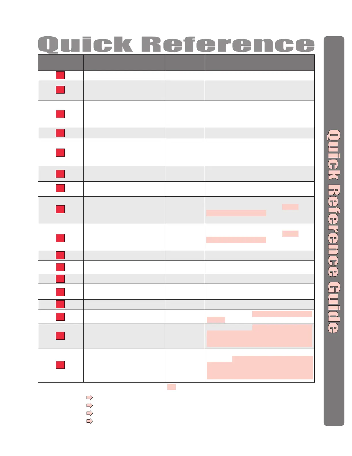
Description of Task Programming Procedure
Programming
Number
61 # (door 1-4) # (relays to activate 0000-1111) #
Order of relay is: relay 4 – relay 3 – relay 2 – relay 1 for an
example if you want relay 4 active you would enter 1000, if
you want relay 1 active you would enter 0001
60 # (device 1-4) # (device type 0-2; 0 = no device,
1 = wiegand card reader or keypad, 2 = RF receiver) #
(door 1-4) #
Delete an Entry Code
57
Assign Each External Access Control
Device a “Door Number”
(Step 1 of 4)
60
Assign “Each” Door Number to One or
More Relays
(Step 4 of 4)
61
Assign Door Use Time Zone
63
57 # (entry code) #
Set the Default Facility Code
73
73 # (0-255) #
Set the Default Card Type
71
71 # (26 or 30) #
Set Relay(s) for AutoCall
70
Assign a Postal Lock Switch to Door No.
69
69 # (door 0-4; 0 = no postal lock) #
70 # (relays to activate 0000-1111) #
Order of relays are 4321
63 # (door 1-4) # (time zone, 0-63) #
D1,D2,D3,D4=Enabled
No Device
Assigned
No Relays
Assigned
D1=Relay 1
D2=Relay 2
D3=Relay 3
D4=Relay 4
64
64 # (device 0-4) # (0-3; 0 = disable,
1 = set device to timed anti-passback,
2 = set device to true anti-passback - entrance,
3 = set device for true anti-passback - exit) #
Set Anti-Passback Entry/Exit for
Specific Devices
74
74 # (0 = disable; 1 = ignore) #
66 # (relay number 1-4) # (activation time, 1-300
seconds) #
Enable/Ignore Facility Code when Card is Used
66
Set Each Relay's “Activation Time”
(Step 3 of 4)
80
Add a Basic Card
81
Add or Edit a Full Function Card
67
Configure an Exit Device (REX)
Disabled
All Relays =“Strike”
All Relays =
10 seconds
R1=Door 1
R2=Door 2
R3=Door 3
R4=Door 4
68
Configure a Door Sensing Device
82
Add a Card Group
DS1=Door 1
DS2=Door 2
DS3=Door 3
DS4=Door 4
Set Each “Relay Type” to get the
Appropriate Response
(Step 2 of 4)
65
65 # (relay 1-4) # (0-5; 0 = unknown, 1 = strike,
2 = shunt, 3 = CCTV, 4 = alarm, 5 = control) #
Door 1
30-bit Cards
0
Ignored
The Pound Key (#) must be used as Data Field Separator and to Save Data at the end of the sequence.
Time must be entered using a 24-hour format
(8AM=0800, 3PM=1500 etc.
)
2 Short Beeps:
Programming input is valid.
1 Long Beep:
Input is not valid.
If you make an error during an entry, press the asterisk key (
*
) to begin again.
Important:
Optional Steps Indicated with a Background, all other steps are Required
67 # (REX number 1-4) # (select REX option: 0 =
disabled, 1 = use your door settings or 2 = use
specific relay(s) 0000-1111) #
Order of Relays are 4321
68 # (sensor number 1-4) # (select sensor option: 0 =
disabled, 1 = use your door settings or 2 = use
specific relay(s) 0000-1111) #
Order of Relays are 4321
80 # (card PIN code) # (facility code) # (card type, 26
or 30) #
81 # (card PIN code) # (facility code) # (card type, 26
or 30) # (schedule for door 1, 0-63) # (schedule for
door 2, 0-63) # (schedule for door 3, 0-63) #
(schedule for door 4, 0-63) #
82 # (card PIN code start range) # (card PIN code
end range) # (facility code) # (card type, 26 or 30) #
(0 = deactivate; 1 = activate) # (schedule for door 1,
0-63) # (schedule for door 2, 0-63) # (schedule for
door 3, 0-63) # (schedule for door 4, 0-63) #
 Loading...