2
INSTALL THE TRANSFORMER
The transformer can be installed inside the control box or it can
be connected to an external receptacle. Follow the instructions
according to your application.
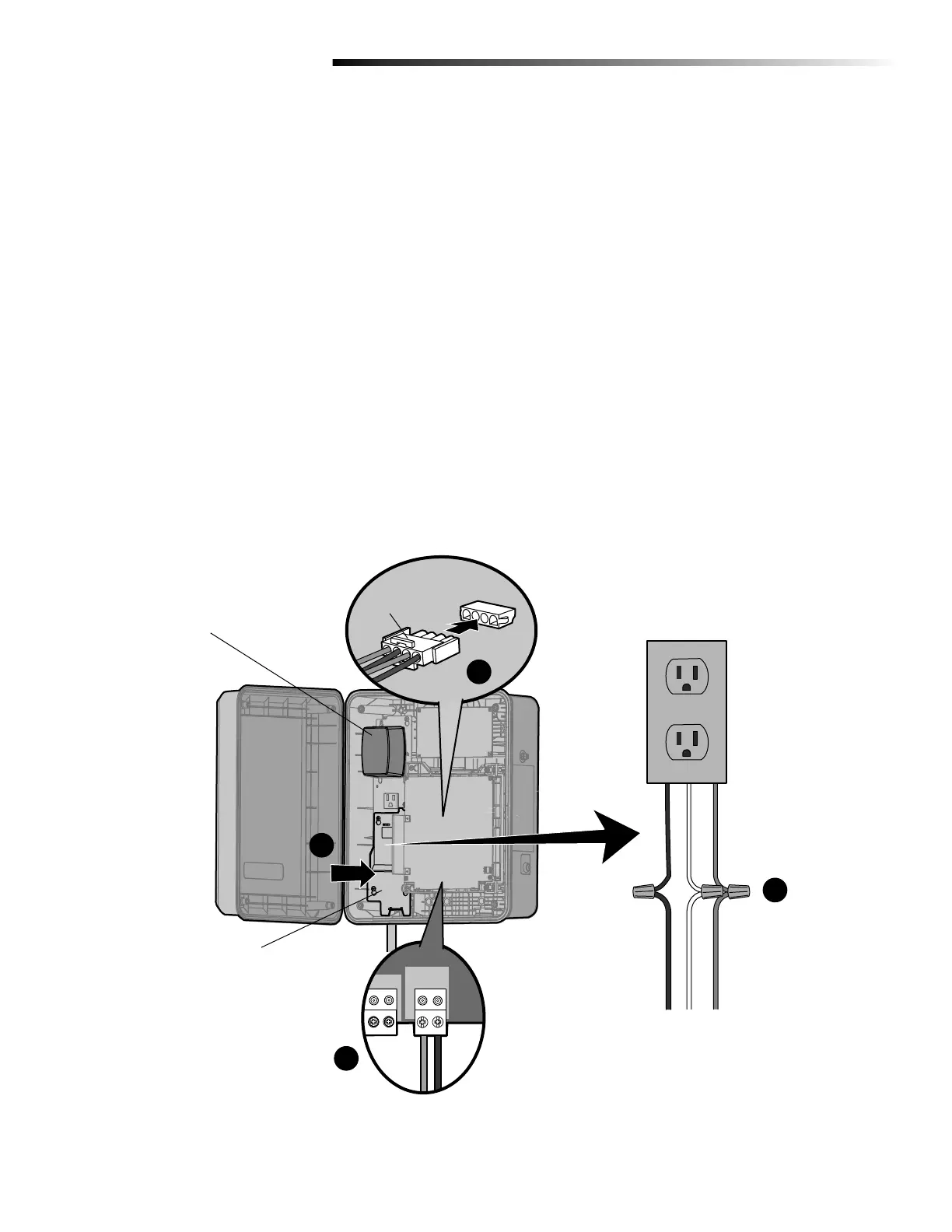
CONTROL BOX INSTALLATION
1 Run the AC power wires to the control box (if applicable).
2 Connect the green wire from the accessory outlet to the
incoming earth ground rod wire using a wire nut (Figure 2-A).
3 Connect the white wire from the accessory outlet to the
incoming NEUTRAL (white) power wire using a wire nut
(Figure 2-A).
4 Connect the black wire from the accessory outlet to the
incoming HOT (black) power wire using a wire nut (Figure
2-A).
5 Install the junction box cover (Figure 2-B). Ensure the wires
are not pinched.
6 Wire the transformer (not provided) to the CHARGER input on
the control board (positive to positive and negative to
negative) (Figure 2-C).
Battery Connector
J15 Plug on
control board
Accessory Outlet
white
black
ground
white
black
ground
Power Wires
Plug-in Transformer
Model APOW3 (not
provided)
Junction Box Cover
black (-)
white (+)
(connect to transformer)
FIGURE 2
A
B
C
D
7 Plug the transformer into one of the accessory outlets.
8 Plug the battery connector to the J15 plug labeled BATT(-)(+)
DC(-)(+) on the control board (Figure 2-D). The control board
will power up. NOTE: You may see a small spark when
plugging the J15 plug into the board.
9 Turn ON AC power to the operator.

 Loading...