3
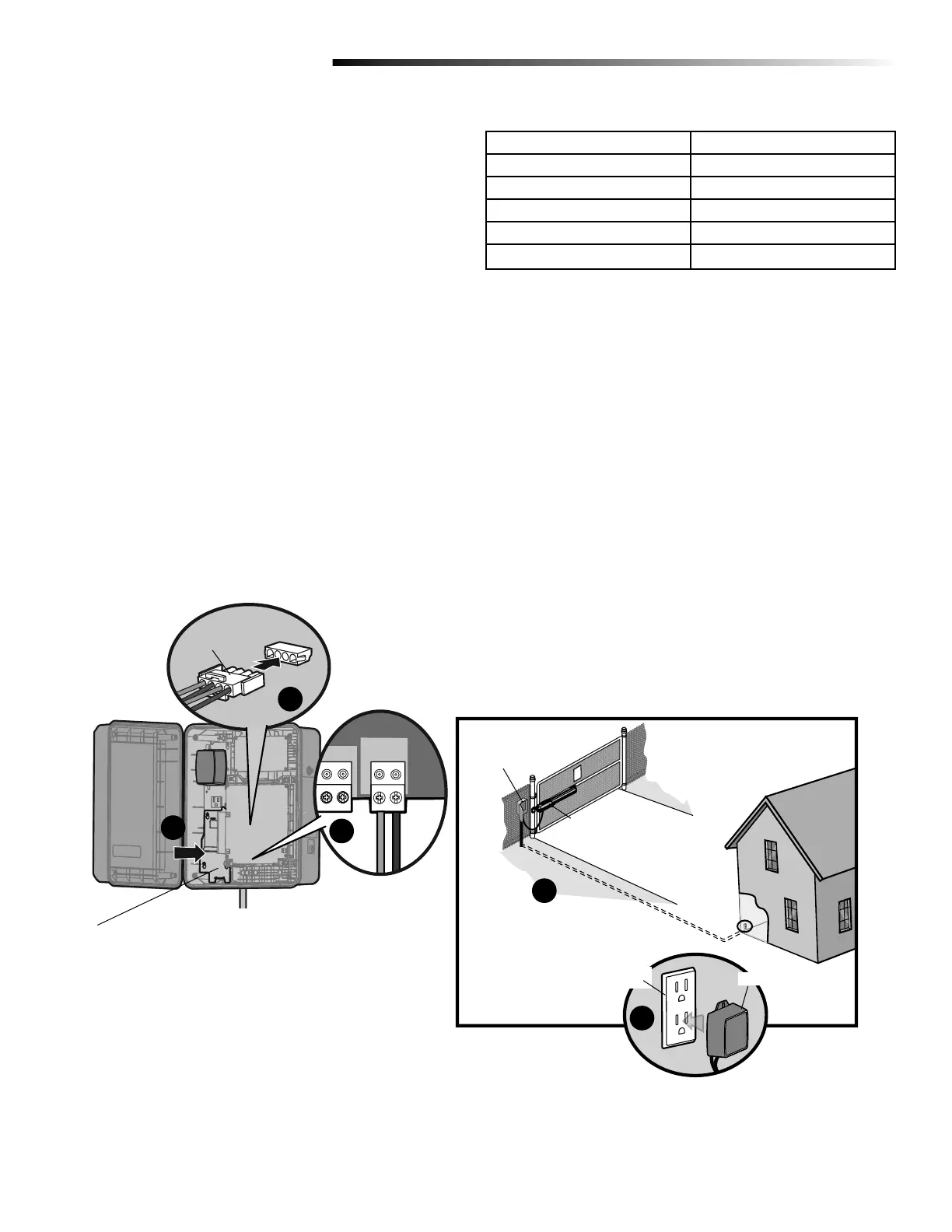
Wire Distance Wire Gauge
65 feet 18
100 feet 16
165 feet 14
265 feet 12
420 feet 10
!
FIGURE 3
Longer wire runs are susceptible to surges and lightning strikes.
Control Box
Operator
Dedicated
Outlet
Transformer
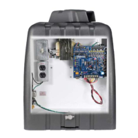
INSTALL THE TRANSFORMER
EXTERNAL RECEPTACLE INSTALLATION
1 Run low voltage wire between the control box and the external
receptacle (Figure 3-A). The transformer must be located in a
dry location that is protected from weather conditions, such
as inside the house or garage.
2 Install the junction box cover (Figure 3-B). Ensure the wires
are not pinched.
3 Wire the transformer (not provided) to the CHARGER input on
the control board (positive to positive and negative to
negative) (Figure 3-C).
4 Plug the transformer into the external receptacle (Figure 3-D).
5 Plug the battery connector to the J15 plug labeled BATT(-)(+)
DC(-)(+) on the control board (Figure 2-E). The control board
will power up. NOTE: You may see a small spark when
plugging the J15 plug into the board.
black (-)
white (+)
(connect to
transformer)
C
A
B
Battery Connector
J15 Plug on
control board
E
D
Junction Box Cover

 Loading...