©2012 The Chamberlain Group, Inc.
01-36760C All Rights Reserved
www.liftmaster.com
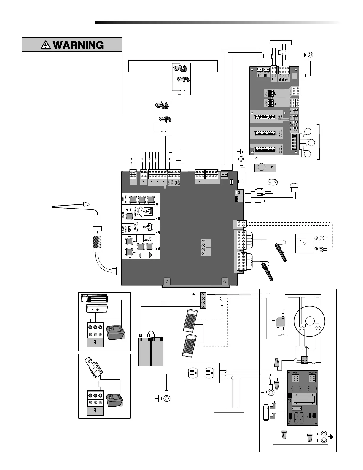
STANDARD CONTROL BOX
WIRING DIAGRAM
LA500 WIRING DIAGRAM PLASTIC E-BOX
(TRANSFORMER RUN)
47-36589-10-D
ECN: 16363
Reference: 06-36238F
09/27/12
Attach to Outlet
Metal Chassis
With a Single Screw
SET OPEN
SET CLOSE
MOVE
GATE
OFF
5
10
60
180
MIN
MAX
(SECONDS)
OFF
ON
OPEN
CLOSE
STOP
INPUT POWER
BATT CHARGING
TIMER
GATE MOVING
BATT LOW
ACC PWR OVLD
DIAGNOSTIC
CODES
STATUS:
SBC
“FIRE
DEPT.”
OPEN
EXIT
SHADOW
CLOSE
EYES/
INTERRUPT
LOCK
N.O.
COM
N.C.
+ -
+ -
ACCESSORY
POWER
ON SW.
EXP.
BOARD
XMITTER
NETWORK
PRESS &
RELEASE
TO BEGIN
SETUP
CLASS 2 SUPPLY
24 VOLTS
1
LIMIT
2
- +
+ -
+ -
CHARGER
Photoelectric Sensors
Photoelectric Sensors
Edge
Edge
J15
Field Wiring
EXPANSION BOARD
Yellow
Blue
Black
Red
+
-
+
-
+ -
BATT
- +
DC
POWER
ID RESET
ALARM
Piezo Alarm
White
White
Purple
Reset Switch
Red
Black
GROUND
BR GRN WT YE BLU RED
BR GRN WT YE BLU RED
Loop Detector
Field Wiring
Wire Loop
Wire Loop
Wire Loop
Field Wiring
N.C.
Brown
Purple
Transformer 200 VA
+
-
-
-
Bridge Rectier
Wire Nut
Gray
Blue
12V 7AH Battery
Black
Red
12V 7AH Battery
To J15
Primary Operator
Secondary Operator
Black
Red
Yellow
White
Red
Orange
N
GND
GND
L
N
Input Power Connection
Input Power Connection
EMI FILTER/SURGE PROTECTION BOARD
L
Switch/5A Breaker
Tranformer Run Kit (Optional)
Accessory Power
Outlets
Attach to Metal Chassis
Black
Black
Red
White
Ground
Connect Outlets
to Transformer
Kit
Maglock
(Optional)
(not provided)
Solenoid Lock
(Optional)
(not provided)
GROUND
Attach to Outlet Metal Chassis
With a Single Screw
Two 12V Solar Panels in Series
+
-
-
+
Black
Red
Black
Red
Transformer
(Optional)
+
-
Blocking
Diode
Coaxial Antenna Cable
Antenna
To protect against fire and
electrocution:
• DISCONNECT power and battery
BEFORE installing or servicing
operator.
For continued protection against fire:
• Replace ONLY with fuse of same
type and rating.
(+)
(-)
(+)
(-)

 Loading...