Do you have a question about the Chamberlain K1A6424-2 and is the answer not in the manual?
Details the intended use of the logic control board for commercial door operators.
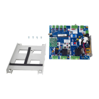
Step-by-step instructions for replacing the logic board, including wiring and connection guidance.
Critical safety precautions regarding electrocution and chemical exposure during installation.
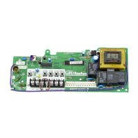
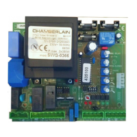
Visual reference identifying key components and connection points on the logic board.
This document describes the Logic Board Replacement Kit (K1A6424-2 for 315MHz and K1A6424-3 for 390MHz) for LiftMaster commercial door operators. The kit is designed for use with all limited duty commercial door operators that utilize a logic control board, such as the MT-5011-E model. A key safety requirement for B2 wiring mode is the installation of a monitored safety device.
The installation process for the logic board is straightforward and emphasizes safety and careful handling of wiring.
The logic board offers various programming options to customize the operator's functionality, including wiring type modes, remote control programming, and a Timer to Close (TTC) feature.
The operator supports two primary wiring type modes:
The operator's factory default is C2 mode if no LMEP device is installed, and B2 mode if an LMEP is present. To switch to C2 mode with an LMEP installed, press and hold LEARN and CLOSE for 3 seconds until the DIAGNOSTIC LED turns off. To revert to standard operation, press and hold LEARN and STOP for 3 seconds until the DIAGNOSTIC LED turns off.
The built-in 315 MHz radio receiver can store up to 20 Security+® remote controls or dip switch remote controls.
Single Button Remote Controls:
3-Button Remote Controls:
Erasing Remote Controls: To erase all learned remote controls, press and hold the LEARN button for over 5 seconds until the DIAGNOSTIC LED flashes rapidly.
The TTC feature allows the operator to automatically close the door after a preset time, adjustable from 5 to 60 seconds. This feature requires an LMEP device to be connected and unobstructed.
Programming TTC:
Clearing TTC:
Timer Defeat: The TTC can be temporarily disabled by pressing the STOP button on the logic board or on the 3-button control station. The TTC will reactivate after the next open cycle.
This device complies with FCC and Industry Canada (IC) rules. Any adjustments or modifications to the receiver/transmitter are prohibited, except for changing the code setting or replacing the battery. There are no other user-serviceable parts. Operation is subject to two conditions: the device must not cause harmful interference, and it must accept any interference received.
| Model Number | K1A6424-2 |
|---|---|
| Category | Control Unit |
| Power Source | Battery |
| Security | Rolling code technology |
| Compatibility | Chamberlain and LiftMaster garage door openers |
| Connectivity | Wireless |