GB-2
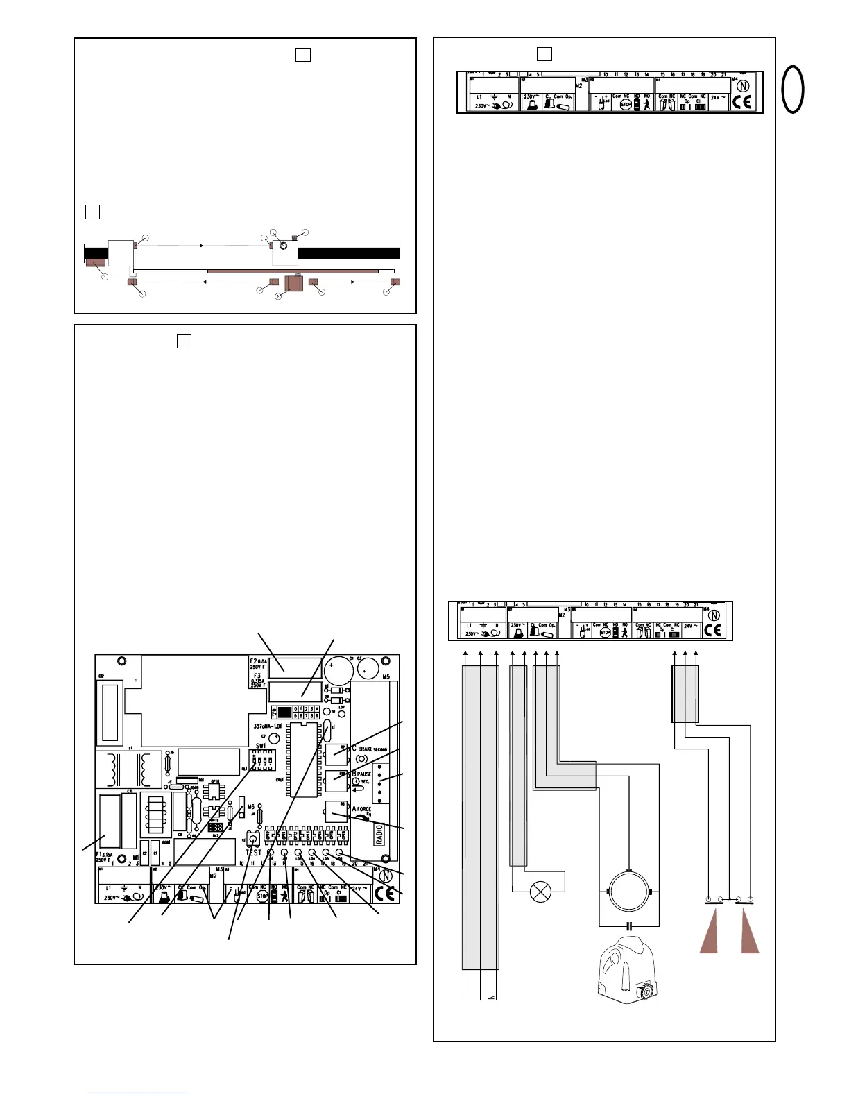
CONNECTIONS
M1 230Volt
1- L L 230V/ 50Hz +/- 10%
2- Earth Supply for control unit, drive,
accessories
3- N (neutral conductor) 230Volt~
4- L
5- L Flashing lamp (230Volt~)
M2
6- L Close
7- N (neutral conductor) Drive connection 230 V AC, 700 VA
max.
8- L Open Capacitor is connected
across 6 and 8
M3
9- LED – Gate status LED
10- LED + Shows whether gate is OPEN or
CLOSED
11- COM (common)
12- STOP (normally closed) Pedestrian button
13- Button A (normally open) A = open gate completely
14- Button B (normally open) B = open gate partially
15- COM (common)
16- LS contact (normally closed) Light barrier connection
M4
17- OPEN (normally closed)
18- COM (common) Limit switch connection
19- CLOSE (normally closed) Pre-installed for "right hand"
20- L Accessories apply 24 V AC ±5%
500 mA
21- L
3
TYPICAL SYSTEM CONFIGURATION
(1) Drive with control unit
(2) Control unit (if installed externally)
(3) Light barrier transmitter
(4) Light barrier receiver
(5) Flashing lamp
(6) Antenna (optional)
(7) Key-operated switch (optional)
(8) Light barrier (optional)
(9) Light barrier (optional)
1
1
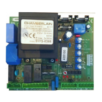
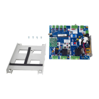
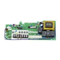
INSTALLATION
(1) F1 Main fuse (230 V)
(2) F2 Additional fuse 24 V AC
(3) F3 Central fuse (logic circuitry)
(4) C Brake
(5) B Pause (gate pauses when open)
(6) M5 Receptacle for radio (model 801719)
(7) A Opening and closing force
(8) LED 5 Limit switch monitoring
(9) LED 6 Limit switch monitoring
(10) LED 4 Light barrier (monitoring)
(11) LED 3 B button input
(12) LED 2 A button input
(13) LED 1 STOP (emergency stop)
(14) LED 7 Diagnostics (general)
(15) M1 ÷ M4 Terminal connection
(16) M6 Accessory connection (not required)
(17) SW1 Program switch (DIP switch)
(18) TEST Test button (opens gate completely)
2
1
2
3
4
5
6
7
8
9
10
11
1213
14
15
16
17
18