13
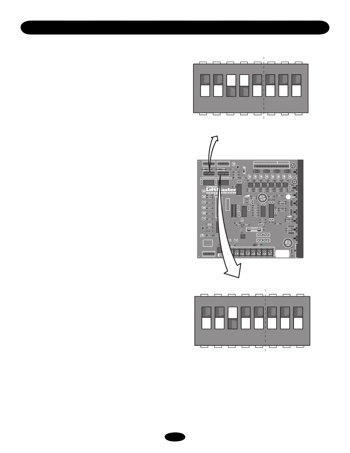
FAST RUN TIMER - SWITCH PACK S1 (1-5)
To change the FAST SPEED run timer, set the dip switches to add
up to the number of feet, minus one foot, for the total feet of
travel across roadway.
Example: If road is 15' wide, then set dip switches to add up to
14 seconds (dips 2, 3, 4 are on) which is 2 seconds + 4 seconds
+ 8 seconds = 14 seconds. You must set FULL SPEED to end
before the end of travel and allow the gate to go to the slow
speed before stopping.
Verify that the FAST SPEED run timer setting slowed down the
gate approximately 1' from the end of travel. If it does not, adjust
the dip switches appropriately.
MODE SELECTIONS - SWITCH PACK S1 (6-8)
SWITCH 6: FAIL SECURE MODE, (VER 6.351 or higher) with ac
power off, in continuous battery back up mode (S2 #8 off) gate
will not auto open if batteries get low. If batteries are low, gate
will stay open after an open command is given.
SWITCH 7: No longer used as of August 16, 2003. To be
redefined.
SWITCH 8: Not used at this time (VER 6.34 or higher only).
CLOSE TIMER - SWITCH PACK S2 (1-5)
On the MEGA SLIDE X the switches 1-5 on S2 are for the closing
timer delay. If S2-7 is on, the gate will auto close by timer.
Default is S2-3 “on” to provide a 4 second delay if activated.
MODE SELECTIONS - SWITCH PACK S2 (6-8)
SWITCH 6: Sets auxiliary open input terminal #4 at J5 to be
pulse open--pulse close (example: residential applications).
SWITCH 7 - AUTO CLOSE TIMER: Default is OFF. When on,
use S2 1-5 to set close time delay.
When close timer is selected, YOU must install vehicle and
pedestrian detection devices. It is strongly recommended that
photoelectric beams (eyes) be installed on BOTH sides of the
slide gate to reduce the possibility of injury to persons that may
attempt to walk through gate opening. Along with the beams, it
is strongly recommended that pressure sensing edges be
installed on the leading edge of the gate panel, and any area
that presents a PINCH POINT or risk of ENTRAPMENT.
SWITCH 8 - AUTO OPEN ON AC POWER FAILURE: When
switch number 8 is in the ON position, the operator will
automatically open the gate approximately 15 seconds after the
loss of power. Once ac power is restored, the operator will
resume normal operation.
TIMERS AND MODE SELECTIONS S1 & S2
1 - - 2 - - 4 - - 8 - -
1
2345678
ON
16
1 - - 2 - - 4 - - 8 - - 16
1
ON
2345678
OFF OFF OFF
OFF
OFF
OFF
ONON
OFF
ON
OFF
OFF OFF
OFF
OFF OFF
24VAC XFMRACC+
HBEAT B AT LO AC POWER
PWR
CNCNO
Aux Relay
R2 R11
D1
Q1
DC
1
1
K1
D11 D12
R13
D14
U19
J4
F3
F4
F1
F2
1A DC
IRD1
R63
J1
ACC– BAT–
BAT– MOV
BAT+ MOTOR
MOTOR
AUX LIMITS
1
J2
J3
J5
M/S
JP2
S3
1
Q2
T2
1234567891
Ø
11 1 2
T1
OPEN 1
D15
C7
X2
C19
D7
OLS
R1
U1
C2
C3
C4
C1
U4
R12
S1
D6
OPEN
D5
BRAKE
D4
CLOSE
D3
CLS
D2
IRD
OPEN 2
D16
R3
Ø
OPEN 3
D17
AUX 4
D18
SAFETY 5
D19
CLOSE 6
D22
BACK 7
D23
SHADOW 8
D24
OPEN
CLOSE
MANUAL
R1
Ø
R9
R38
R15
R37
C8
C2
Ø
C12
U12
U1
Ø
+
R8
R7
R6
R5 U2
U3
CPU
U5
U6
U7
X1
R4
R3
D8
T4
T3
T6
T5
T8
T7
C15
C2
D27
Q6
Q5
F5
C22
C18
U18
1 2 3 4 5 6 7 8
S2
1 2 3 4 5 6 7 8
D1
Ø
R14
R18
R21
R24
R36
R42
R47
R53
R35 R41 R46 R5
Ø
R61
C16
R17
R16
D29
Q4
D28
D26
C6
D25 – B2 +
U8 U9
U16
U11 U13 U14 U15
D9
R23
R22
R26
R25
R19
B1
R2
Ø
C5
+
+
R34
R33
R4
Ø
R39
R45
R44
R58
DX3
R49
R48
R43
R51
WARNING FOR
CONTINUOUS
PROTECTION
AGAINST FIRE
REPLACE ONLY
WITH THE SAME
TYPE AND RATING
OF FUSE
R43
R6
Ø
R59
D21
D2
Ø
R62
DX1
TR
DX4
R57
R56
C13
DX2
R55
Mode Selection 6-8
Close Timer 1-5
Seconds - -
Shows
Default
Settings
S2
Mode Selection 6-8
Fast Run Timer 1-5
Seconds - -
Shows
Default
Settings
S1