Rev C Doc 6001565 Page 17 of 31
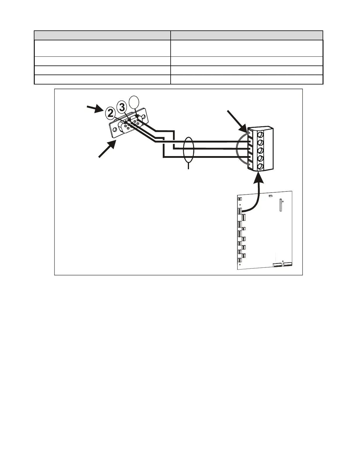
DB9S Connections.
PIN NUMBER ON DB9S TERMINAL ON MAIN CIRCUIT BOARD TB 2
Place one jumper between pins 4 and 6 and
another between pins 7 and 8.
Place a jumper between pins 1 ("cts") and 5 ("rts").
2 ("receive data") RS-232 out ("out")
5 ("signal ground") GROUND
3 ("transmit data") RS-232 in ("in")
TB2
Jumper
CTS to RTS
CTS
OUT
GND
IN
RTS
INFINITY
PROCESSOR
BOARD
DB9S
(Back View)
Use 18-24 AWG,
3-Conductor, Shielded Cable
(30 Feet Max. Length)
DB9S
PIN #
5
Jumper:
Pins 4 to 6
Pins 7 to 8
1565F2
Jumpers
not shown
Figure 12: DB9S Connections