Rev C Doc 6001565 Page 19 of 31
Connect the Infinity and the printer as follows:
DB25 Connections.
PIN NUMBER ON DB25 TERMINAL ON MAIN CIRCUIT BOARD TB2
Place one jumper between pins 4 and 5 and
another between pins 6 and 20
Place one jumper between pins 1 (CTS) and 5
(RTS).
3 ("receive data") RS-232 (“out”)
7 ("signal ground") GROUND
2 (“transmit data”) RS-232 (“in”)
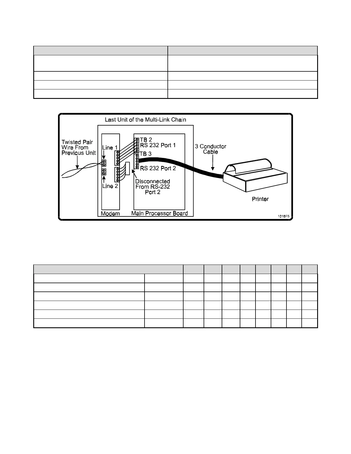
Figure 14: Printer Connected to Last Unit of Multi-Link Chain
The proper switch settings for the Okidata 184 Turbo are shown below:
Switch Settings for the Okidata 184 Turbo
SWITCH # 1 2 3 4 5 6 7 8
Main Board Switch Bank ON X X X
OFF X X X X X
Serial Board Switch Bank 1 ON X X X X X X X
OFF X
Serial Board Switch Bank 2 ON X X X X X X X
OFF X
NOTE: The settings for switches 1, 2, and 3 on Serial Board Switch Bank 2 are proper only for the
4800 baud rate. Please consult the printer manual for the settings to select other baud rates.