Doc 6001565 Rev C
TABLE OF FIGURES
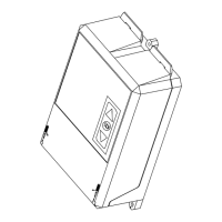
Figure 1: Mounting the Cabinet ....................................................................................................... 3
Figure 2: Telephone Interface Board Connections ..........................................................................5
Figure 3: Infinity Circuit Board Connections (1100023 Board) ......................................................... 6
Figure 4: Infinity Circuit Board Connections (1100072 Board) ......................................................... 7
Figure 5: Optional CCTV Unit..........................................................................................................8
Figure 6: Connecting Multiple Units Via RS-232 Ports .................................................................... 9
Figure 7: Connecting Multiple Units Through Short-Haul Modems ................................................ 10
Figure 8: RS232 Connections with Dual Short-Haul Modems and Multiple Units........................... 10
Figure 9: Hooking Up an External Modem..................................................................................... 14
Figure 10: Direct Connection Between Computer and Unit 1 of Multi-Link Chain .......................... 16
Figure 11: DB25 Connections .......................................................................................................16
Figure 12: DB9S Connections....................................................................................................... 17
Figure 13: PC/Terminal Connected to First Infinity in a Chain Via Stand Alone Modem ................ 18
Figure 14: Printer Connected to Last Unit of Multi-Link Chain ....................................................... 19
Figure 15: Auxiliary Relay Module ................................................................................................. 24
Figure 16: Telephone Interface Board, Adjustments and Indicators .............................................. 26
Figure 17: CCTV Power Supply Board J1 Connector .................................................................... 29
COPYRIGHT 2002
ALL RIGHTS RESERVED
This document is protected by copyright and may not be copied or adapted without the prior written
consent of Sentex. This documentation contains information which is proprietary to Sentex and such
information may not be distributed without the prior written consent of Sentex. The software and
firmware included in the Sentex Infinity system as they relate to this documentation are also protected by
copyright and contain information proprietary to Sentex.
Sentex Systems
Chatsworth, CA
Visit us at www.sentexsystems.com