EasyManua.ls Logo

Chamberlain SLY500E-120 User Manual

Chamberlain SLY500E-120
6 pages
To Next Page IconTo Next Page
Page #1 background imageLoading...
Page #1 background image
GB-1
Contents: General Information on
Installation and Use:
Details of Contents: Page 1
Before You Begin: Page 2
Check List: Page 2, figs. -
Overview of Installation: Page 2, fig.
Installation of Rack Bar:
Page 2, fig.
Electrical Installation: figs. -
Installation of Base Plate: Page 2
Mounting Drive on Base Plate:
Page 2, figs. +-A
Drive Release Mechanism:
Page 2, fig.
Limit Switches: Page 2, fig.
Light Barrier:
Page 3, figs. - B
Flashing Lamp: Page 3, figs. - A
External Antenna:
Page 3, figs. - A
Initial Operation: Page 3
Maintenance Work: Page 3, figs.
Typical System Set-up:
Page 4
Teaching in Remote Control:
Page 5, fig.
Technical Data: Page 3
CE Conformity Certificate: Page 4
Contents in SLY500-120 packs
(1) Drive motor (1x)
(2) Capacitor (pre-installed) (1x)
(3) Limit switch A or (1) (1x)
(4) Limit switch B or (2) (1x)
(5) Base plate for drive motor (1x)
(6) Accessories bag
Additionally for models: SLY500E-120
(7) Control unit with housing (pre-installed as standard
for right-hand installation) (1x)
Additionally for models: SLY500K-120
(8) Flashing lamp (1x)
(9) Light barrier (pair)
(10) Radio receiver (pre-installed) (1x)
(11) Handset 433MHz (2x)
(12) Key-operated aerial (1x)
(13) External Antenna (1x)
READ THESE IMPORTANT SAFETY INSTRUCTIONS BEFORE STARTING WORK
CAUTION! Only use the drive if you have a clear view of
the gate, if there are no obstacles in the gate's path and
the drive is correctly adjusted. Children should not be
playing near the gate when the drive is to be used.
Disconnect the gate drive from the power supply before
any repairs are made.
This symbol means 'Caution!'; it is a sign that compliance with the given instruction is required as non-compliance can lead to
persons being injured and property damaged. Please read such warnings carefully.
This gate drive has been designed in such a way and tested to ensure that it offers adequate safety providing its installation
and use exactly comply with the following safety instructions.
Non-compliance with the following safety instructions can lead to persons being seriously injured or property badly damaged.
The sliding gate drive can be activated via push-buttons, key-operated switches, keyless switches (radio) or remote control; once the
drive has been disengaged with the appropriate key, the gate can be opened by hand. The sequence of functions initiated by a
command issued via a remote control, push-button, etc. depends on how the control's electronic system has been set.
Electric cables should be laid in accordance with local
building and installation regulations and may only be
connected to a properly earthed mains supply by a
qualified electrician.
When installing the drive, sufficient clearance must be left
between the item driven and the surrounding parts of the given
building (e.g. a wall) due to the opening movement of the item
driven.
Automatically controlled equipment must be
disconnected from the mains when maintenance work
e.g. cleaning is being performed.
In the case of a permanently laid installation, an
isolating device must be fitted to ensure that all the
connections can be isolated via a switch (min. 3mm
contact opening clearance) or a separate fuse.
Take great care when working with tools and
hardware. Never wear rings, watches or loose clothing
when you are performing installation or repair work on
the gate.
Make sure that the persons installing, servicing or using
the drive observe these instructions. Keep the
instructions in a safe yet readily accessible place.
Please remove all locks fitted to the gate in order to avoid
damaging the gate.
It is important to keep the gate in good working order.
Gates that do not open and close smoothly and fully
should be repaired without delay. Do not try to repair
the gate yourself. Have it done by a person qualified.
Keep any extra items of equipment and accessories out of
the reach of children. Do not allow children to operate the
push-buttons or remote control. Serious injuries can be
caused by a gate that is closing.
Once installation has been completed, you must check
that the mechanism is correctly adjusted and that the
drive, safety system and emergency release all
function as they should.
Once the drive has been installed, the gate must be
tested to ensure that there is no risk of persons trapping
or cutting themselves.
If the gate system is fitted with a slip-gate, the drive
may not be started or move further until the slip-gate
has been closed properly.
1
4
5
7
8
9 9
10 10
11 11
12
2
3
6
6
13
A
C
Question and Answer IconNeed help?

Do you have a question about the Chamberlain SLY500E-120 and is the answer not in the manual?

Chamberlain SLY500E-120 Specifications

General IconGeneral
BrandChamberlain
ModelSLY500E-120
CategoryGate Opener
LanguageEnglish

Summary

Important Safety Instructions

General Safety Precautions

Covers essential safety guidelines for installation, operation, and maintenance to prevent injury and damage.

Before You Begin

Pre-Installation Checklist

Ensures all parts are present and the gate system is in good working order before starting installation.

Installation Overview

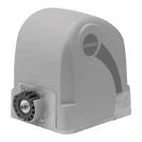
Provides a general guide on drive placement and rack bar fitting relative to the gate.

Drive Base Plate Installation

Details on concreted or welded base plate placement, including height and depth considerations.

Motor and Gear Unit Mounting

Instructions for fitting the drive onto the base plate with proper alignment to the rack bar.

Rack Bar Mounting

Guidance on fitting the rack bar to the gate for optimal engagement with the drive's cog wheel.

Drive Release Mechanism

Explains how to operate the manual release mechanism for power outages.

Limit Switches Fitting

Describes the correct placement and connection of limit switches for gate travel.

Limit Switch Functionality Test

Procedure to test the limit switches and control unit response for correct gate operation.

Component Installation and Technical Data

Infrared Sensor Installation

Details on installing infrared sensors for safety, including placement and wiring.

Flashing Lamp Installation

Guidance on installing the flashing lamp for visual safety warnings.

Key Switch Installation

Instructions for installing and wiring the key switch for gate activation.

External Antenna Installation

Information on installing an optional external antenna to extend remote control range.

Initial Operation Checks

Steps to perform before initial electrical operation and general safety compliance.

Maintenance Work

Routine checks for gate hardware and drive functionality, emphasizing smooth operation.

Technical Data Summary

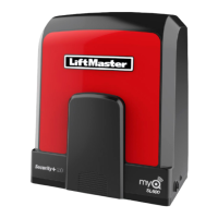
Key specifications for the SLY500 drive and CB2-120 control unit.

System Setup and Operation

Typical System Setup Diagram

Illustrates the connection of major components in a typical sliding gate system.

Installation Connections Plan

Detailed wiring diagram showing terminal assignments for control unit connections.

Operating Programmes

Description of four operating modes selectable via DIP switches for different functionalities.

Settings and Adjustments

Guide to setting potentiometers for force, pause time, and brake.

Operation and Troubleshooting

LED Monitors and Error Analysis

Explanation of system status LEDs for error detection and function monitoring.

Fuse Protection

Details on fuse types and their functions for protecting the control unit and drive.

Default Settings and Initial Operation

Steps for initial setup, including force adjustment and testing functionality.

Remote Control Programming

Instructions for teaching and deleting remote control codes to the system.

Declaration of Conformity

Statement of compliance with relevant EU directives and standards.

Related product manuals