EasyManua.ls Logo

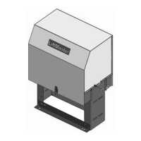
Chamberlain LiftMaster Professional SL585 User Manual

Chamberlain LiftMaster Professional SL585
40 pages
To Next Page IconTo Next Page
Page #1 background imageLoading...
Page #1 background image
CONTROLLER BOARD
GL
Serial # ________________________
(located on electrical box cover)
Installation Date __________________
2 YEAR WARRANTY
MODELS SL585 AND SL595 ARE FOR VEHICULAR
PASSAGE GATES ONLY AND ARE NOT INTENDED FOR
PEDESTRIAN PASSAGE GATE USE
MODEL SL585
HEAVY DUTY SLIDE GATE OPERATOR
MODEL SL595
HEAVY DUTY, HARSH ENVIRONMENT
SLIDE GATE OPERATOR
Question and Answer IconNeed help?

Do you have a question about the Chamberlain LiftMaster Professional SL585 and is the answer not in the manual?

Chamberlain LiftMaster Professional SL585 Specifications

General IconGeneral
BrandChamberlain
ModelLiftMaster Professional SL585
CategoryGate Opener
LanguageEnglish

Summary

UL325 Compliance and Safety

Entrapment Protection Types

Describes six types of safety devices for preventing gate entrapment.

Entrapment Protection Requirements

Details required primary and secondary entrapment protection for UL325 classes.

Safety Installation Guidelines

General Installation Safety

Provides critical safety instructions for installing gate operators and systems.

Sensor Placement Guidelines

Specifies placement for non-contact and contact sensors to prevent entrapment.

Gate Safety Precautions

Roller Gate Safety

Highlights pinch points and injuries related to open roller gates.

Power Wiring and Wire Gauge

Wiring Specifications Chart

Provides recommended wire gauges and maximum distances for single and three-phase power wiring.

Installation Procedures

Electrical Box and Power Wiring

Operator Adjustments and Testing

Entrapment Protection Setup

Control Board and Entrapment Settings

Programming Operator Settings

DIP Switch S1 Settings

Configuration options for timer, gate type, and operation direction using DIP switch S1.

DIP Switch S2 Settings

Configuration options for maglock and warning alarms using DIP switch S2.

Accessory and Control Wiring

Grounding and Surge Protection

Earth Ground Rod Installation

Procedure and importance of installing an earth ground rod for safety.

Operation and Maintenance Schedule

Key Safety Instructions

Crucial safety guidelines for operating and maintaining the gate operator.

Operator Components and Features

Control Board Diagnostics and Troubleshooting

Troubleshooting Common Faults

Operator Not Running or Slow

Addresses issues where the operator fails to run, runs slowly, or contactors chatter.

Advanced Troubleshooting Scenarios

Master/Second and Direction Issues

Solutions for dual gate system failures and incorrect motor direction.

Stops, Alarms, and Input Errors

Addresses issues like motor stopping, alarms, and programming errors for gate inputs.

Single Phase Wiring Diagrams

Single Phase Connections

Detailed schematic and notes for wiring single phase 115V/208V/230V operators.

Single Phase Electrical Schematics

Single Phase Wiring Schematic

Visual representation of single phase wiring connections for the operator.

Three Phase Wiring Diagrams

Three Phase Connections

Detailed schematic and notes for wiring three phase operators (230V, 460V, 575V).

Three Phase Electrical Schematics

Three Phase Wiring Schematic

Visual representation of three phase wiring connections for the operator.

Related product manuals