Do you have a question about the Chamberlain LiftMaster Professional SL595 and is the answer not in the manual?
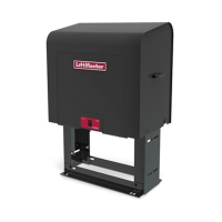
Details dimensions and horsepower specifications for the LiftMaster SL585 gate operator.
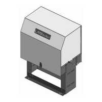
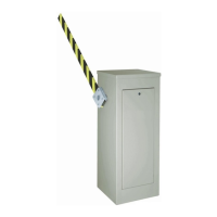
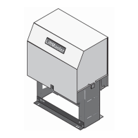
Details dimensions and horsepower specifications for the LiftMaster SL595 gate operator.
Guidance on selecting entrapment protection devices compliant with UL325 standards.
Defines the required entrapment protection types for different UL325 installation classes.
Provides essential safety rules for gate operator installation, including control placement and user access.
Guidelines for positioning entrapment sensors and warning signs for safe gate operation.
Illustrates recommended placement for entrapment protection devices on slide gate systems.
Diagrams showing entrapment device locations for commercial slide gate installations.
Addresses pinch-point risks on roller gates and methods for guarding exposed components.
Instructions for warning sign placement and restricting gate use to vehicles only.
Details wire gauge requirements based on motor horsepower and distance for safe power wiring.
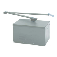
Step-by-step guide for installing the SL585 operator on a concrete pad.
Instructions for both existing pad installations and new concrete pad preparation.
Guidance for adapting existing post installations for SL585/SL595 operators.
Steps for properly installing posts and mounting the operator for SL585/SL595.
Procedure for mounting gate brackets and threading the drive chain.
Notes on chain tension and potential bracing for long cantilever gates.
Details on power wiring connections for single and three-phase operators.
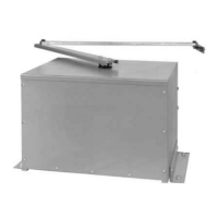
Instructions for engaging and disengaging the manual disconnect lever.
Procedure for setting the open and close limit switch positions for the gate operator.
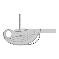
Steps to correctly align the RPM sensor for the entrapment protection system.
Steps to verify proper gate operator function and safety settings after installation.
Guidance on setting force control and secondary entrapment protection inputs.
Details on configuring the control board for edge or photo eye inputs during opening.
Details on configuring the control board for edge or photo eye inputs during closing.
Diagram identifying key components and terminals on the gate operator control board.
Configuration for the auto-close timer feature and its relation to the potentiometer.
Setting the operator for slide or swing gate type and opening direction.
Explanation of the 'Save' switch for storing and locking programmed settings.
Wiring diagram for connecting controls and accessories to the single-phase electrical box.
Instructions for setting security modes and output durations for the radio receiver.
Procedure to clear all previously programmed remote controls from the receiver.
Wiring instructions for remotely mounted stop/reset controls and soft open inputs.
Wiring for override controls, safety loop inputs, and shadow loop inputs.
Configuration and wiring for operating two gate operators in a master/second setup.
Essential safety warnings and steps for properly installing an earth ground rod.
Explains the operation of the SAMS and provides wiring instructions for system integration.
Critical safety warnings and guidelines for operating and maintaining the gate operator.
Recommended checks for components and general maintenance tips.
Procedure for adjusting the friction clutch to prevent gate damage during obstructions.
Details on the Motor Learn function for setting force control profiles.
Guidance on setting the force control potentiometer for optimal gate operation.
Explanation of diagnostic LEDs and codes for identifying operator issues.
Common causes and fixes for when the gate operator does not start.
Troubleshooting steps for contactors that chatter during operator movement.
Diagnosing issues causing slow operation or internal overload trips.
Resolving issues related to communication failures between master and second operators.
Troubleshooting problems with gate direction, stopping, and immediate opening.
Addressing issues with motor learning, programming changes, and sensor inputs.
Wiring diagrams for installing the heater accessory on different voltage operator models.
List of replacement parts available for the self-regulating heater accessory.
Key notes, terminal descriptions, and component identification for single-phase wiring.
Key notes, terminal descriptions, and component identification for three-phase wiring.
List of individual part numbers and descriptions for the SL585 model.
Catalog of service kits available for common repairs and maintenance of the SL585.
Parts that may vary by configuration or model, such as on/off switches.
List of parts not depicted in the accompanying diagrams, such as manuals and accessories.
List of individual part numbers and descriptions for the SL595 model.
Catalog of service kits available for common repairs and maintenance of the SL595.
List of parts not depicted in the accompanying diagrams, such as manuals and accessories.
List of individual components found within the electrical box assembly.
List of variable parts for the electrical box, including overload ratings.
Service kits available for the electrical box, such as limit shaft kits.
Details on acceptable photo-electric sensors for secondary entrapment protection.
Information on acceptable sensing edge devices for secondary entrapment protection.
Information on how to order replacement parts and contact customer support.
| Type | Slide Gate Opener |
|---|---|
| Power | 1/2 HP |
| Drive System | Chain Drive |
| Warranty | 2 years |
| Security | Security+ 2.0 |
| Battery Backup | No |
| Power Source | AC |
| Remote Control | Yes |
| Operating Temperature Range | -4°F to 140°F |