Do you have a question about the Chamberlain LiftMaster Professional SL585GL and is the answer not in the manual?
Discusses selection of safety accessories for entrapment protection.
Details entrapment protection requirements based on UL325 installation classes.
Guidelines for placing warning signs to prevent injury or death from moving gates.
Specifies wire gauges and installation guidelines for operator power wiring.
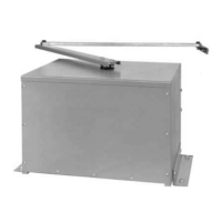
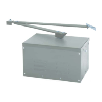
Instructions for installing the gate operator on a concrete pad.
Details conduit knockouts and pass-through holes on the electrical box.
Details wiring for single and three-phase operators via the on/off switch.
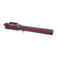
Procedures for engaging and disengaging the manual disconnect lever for gate movement.
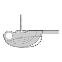
Procedure for setting the gate's open and close limits using limit nuts.
Steps to align the RPM sensor for the entrapment protection system.
Steps to test gate operation and safety features after installation or adjustments.
Instructions for replacing the gear box fill plug with a vented plug.
Configuration of primary and secondary entrapment protection systems for UL325 compliance.
Configuring edge or photo sensors for gate opening and closing protection inputs.
Diagram and labeling of the gate operator's control board components.
Configuration options for timer to close, slide/swing, and left/right operation using DIP switch S1.
Configuration options for Maglock and Warning alarm features using DIP switch S2.
Instructions for setting security mode and output duration for the universal receiver.
Configuring the receiver for HIGH or NORMAL security modes and managing remote codes.
Setting the receiver output contacts for momentary or constant closure.
Procedure to pair handheld remotes with the gate operator's receiver.
Wiring instructions for stop/reset control stations to the operator's control box.
Wiring for the soft open input, accepting devices like entry systems or keypads.
Wiring for hard open/close override inputs for emergency control.
Wiring for safety loop inputs, including interrupt and shadow loop functions.
Configuration and wiring for master/second operator setups in dual gate systems.
Describes the sequence of operations for a two-gate access management system.
Wiring instructions for connecting the BG770 barrier gate to the SL585/595 for SAMS control.
Critical safety guidelines to reduce the risk of severe injury or death during operation.
Checklists for routine maintenance tasks performed at 3, 6, and 12-month intervals.
Description of the brake's function in minimizing gate over-travel and preventing back driving.
Explanation of the friction clutch's role in preventing damage during obstructions.
Procedure to program the control board to the operator's specific motor RPM profile.
Setting the force control pot for proper gate travel and obstruction reversal.
Interpreting diagnostic LEDs and codes for troubleshooting operator faults.
Explanation of various troubleshooting LEDs indicating operational status and faults.
Diagnosing and fixing issues when the operator does not run or respond to commands.
Troubleshooting causes for contactor chatter during operator startup.
Identifying reasons for slow operation or overload trips, including power supply and motor issues.
Resolving issues with dual gate systems where one operator is not functioning.
Troubleshooting causes for the operator stopping and reversing unexpectedly, like entrapment settings.
Diagnosing why the motor runs but the gate doesn't move, or the operator alarms.
Correcting incorrect gate movement direction, often due to power phasing.
List of individual components found within the electrical box assembly.
Available service kits for the electrical box, including limit shaft kits.
| Brand | Chamberlain |
|---|---|
| Model | LiftMaster Professional SL585GL |
| Category | Gate Opener |
| Language | English |