EasyManua.ls Logo

CHAMPIONX WELLMARK DigiMax - User Manual

CHAMPIONX WELLMARK DigiMax
7 pages
Print Icon
To Next Page IconTo Next Page
Loading...
1 REVISION 26-AUG-2021
Wellmark Chemical Injection Solutions
11122 WEST LITTLE YORK RD
HOUSTON, TX 77041
Wellmark Website
Wellmark Mobile Support Site
(713) 466-3552
DigiMax Pump Controller
WELLMARK GENERAL PURPOSE DIGIMAX, 12VDC & 115VAC PUMPS
OPERATION/PROGRAMMING INSTRUCTIONS
FEATURES
The DigiMax controller is designed to control chemical injection rates through
intermittent motor control. The 12VDC version is designed to be operated in off-
the-grid battery powered systems for upstream wellsite chemical injection. A
115VAC version is also available for applications where power is available.
Control Features Include
Auto Injection Mode Enter injection rates directly using a
quarts/day input value. The controller will use the physical
characteristics of the pump and motor to determine cycle timing.
Manual Injection Mode Directly enter ON and OFF timing to
manually controller injection rates and cycle timing.
Temperature Injection Includes standard temperature sensor for
temperature-switched injection. Save chemical by disabling flow as
temperatures rise above a user defined setpoint.
Serial Communication Modbus RTU communication via 2-wire
RS485 connection.
Onboard HMI 8x2 LCD screen with 4 capacitive touch sense buttons
for local programming.
Voltage Monitoring (12VDC Versions) Measures voltage
continuously, which may be used to help predict solar application
power failures when connected to a user’s SCADA system.
Cycle Totalizer Totalizes number of cycles ran to help analyze
injection rates. Can be manually reset.
Low Power Screen backlight timeout conserves power when not in
use.
All programming selections made are retained upon power failure. Shutting the
main power switch off, or losing power will not affect controller settings upon
restart.
Contents
Specifications……………………………………………………………………………………….....
1
Basic Operation……………………………………………………………………………………..
1
Viewing Current Settings………………………………………………………………….
1
Setting Injection Mode and Rate……………………………………………………
2
Starting the Pump in Auto Mode………………………………………………
2
Starting the Pump in Manual Mode………………………………………….
2
Pump Override…………………………………………………………………………
2
Advanced Programming……………………………………………………………………………
3
Adjusting Settings in the Programming Sub-Menu……………………......
3
Resetting the Cycle Counter……………………………………………………………..
3
Calibrating Temperature and Voltage……………………………………………….
3
Communication………………………………………………………………………………………
4
Settings…………………………………………………………………………………………….
4
Modbus Map…………………………………………………………………………………….
4
Troubleshooting……………………………………………………………………………………..
4
Replacement Parts……………………………………………………………………………
4
Basic Troubleshooting……………………………………………………………………….
4
Pump Displacement and Timer Settings…………………………………………………….
5
General Pump Specifications…………………………………………………………….
5
Manual Mode On / Off Times…………………………………………….…………….
5
12VDC, 30RPM Small Motor……………………………………………………..
5
12VDC, 64RPM Large Motor………………........................................
6
115VAC, 60 RPM Motor (General Purpose)………………………………..
7
Specifications
Electrical Specifications
Specification
12VDC Control
115VAC Control
Input Voltage
12VDC Nom +/- 3VDC
115VAC, 60Hz, Single
Phase
Max Output Power
180W
345W
Max Current
15A @ 12VDC
3A @ 115VAC
Storage Temp Range
-30C to 70C
Operating
Temperature Range
-20C to 70C
Basic Operation
Viewing Current Settings
The DigiMax controller uses capacitive-sensing buttons. There is no general
contact with the buttons and only requires a light touch. When a button is
pressed the LED above it will illuminate, notifying the user that the input was
registered.
While in normal running mode, the DigiMax will cycle through a series of “Idle
Screens” to display current settings. Idle screens will vary based on the injection
mode settingpressing any of the keys will cycle through the idle screens.
Manual Mode Screens
Auto Mode Screens
MOTOR
Current Cycle ON or OFF Time Remaining (Seconds)
MTR SIZ (Motor Size)
Motor Output Speed (RPMS)
PLG SIZE (Plunger Size)
1/4”, 3/8”, or 1/2” Diameter
PIN POS (Pin Position)
1, 2, or 3
CYCLES
Total Number of Cycles Recorded since Reset
QTS/DAY (Quarts per Day)
Flow Rate Setpoint (Qts/Day)
TEMP MOD (Temperature Mode)
ON (Enabled) or OFF (Disabled)
TEMP SP (Temperature Setpoint)
Setpoint in °F (Current Temp also Displayed in °F)
VOLTAGE*
Current voltage in V
* Voltage output only displayed on 12VDC controllers
Question and Answer IconNeed help?

Do you have a question about the CHAMPIONX WELLMARK DigiMax and is the answer not in the manual?

Summary

FEATURES

Specifications

Electrical Specifications

Details electrical input voltage, output power, and current ratings for the controller.

Basic Operation

Viewing Current Settings

Describes how to view the current operational settings and parameters displayed on the controller.

Setting Injection Mode and Rate

Starting the Pump in Auto Mode

Step-by-step guide to configure the controller for automatic injection based on daily rate.

Starting the Pump in Manual Mode

Steps to set ON/OFF times for manual pump control and cycle timing.

Pump Override

Instructions for enabling pump output for a limited time for priming purposes.

Advanced Programming

Adjusting Settings in the Programming Sub-Menu

Detailed steps to access and modify advanced settings like motor size and communication.

Resetting the Cycle Counter

Procedure to reset the total cycle count recorded by the controller.

Calibrating Temperature and Voltage

Guide for calibrating temperature and voltage readings for increased accuracy.

Communication

Modbus Map

Table detailing Modbus registers and coils for serial communication.

General Issues

Display Difficult to Read

Explains potential display issues in cold temperatures and expected behavior.

Pump does not run

Lists common checks and causes for the pump failing to operate.

Pump not injecting the correct amount

Provides guidance on diagnosing and correcting issues with incorrect injection volumes.

Troubleshooting

Replacement Parts

Lists part numbers and descriptions for common replacement components.

Pump Displacement & Timer Settings

General Pump Specifications

Table showing plunger area, stroke length, displacement, and max flow rates for different motors.

Manual Mode On; Off Times

Table providing ON/OFF time settings for manual mode based on Qts/Day and plunger size.

Overview

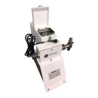
The DigiMax Pump Controller, manufactured by Wellmark Chemical Injection Solutions, is a versatile device designed to regulate chemical injection rates through intermittent motor control. It is available in two main versions: a 12VDC model optimized for off-the-grid battery-powered systems common in upstream wellsite chemical injection, and a 115VAC model for applications where grid power is available.

Function Description:

The primary function of the DigiMax controller is to precisely control chemical injection. It achieves this by managing the ON/OFF cycles of a pump motor. The controller offers both automatic and manual injection modes, allowing for flexible operation tailored to specific application needs. In Auto Injection Mode, users input desired injection rates in quarts per day, and the controller automatically calculates and implements the necessary pump cycle timing based on the pump's physical characteristics and motor specifications. Manual Injection Mode provides direct control over the pump's ON and OFF timing, enabling users to fine-tune injection rates and cycle timing manually.

A key feature is Temperature Injection, which incorporates a standard temperature sensor to enable temperature-switched injection. This allows for chemical savings by disabling flow when temperatures rise above a user-defined setpoint. The controller also includes Modbus RTU serial communication via a 2-wire RS485 connection, facilitating remote read/write control when integrated with a user's SCADA system. An onboard Human-Machine Interface (HMI) features an 8x2 LCD screen and four capacitive touch-sense buttons for local programming and interaction. For 12VDC versions, continuous Voltage Monitoring is provided, which can help predict solar application power failures when connected to a SCADA system. A Cycle Totalizer tracks the total number of pump cycles, aiding in injection rate analysis, and can be manually reset. To conserve power, especially in battery-powered systems, the screen backlight includes a timeout feature. All programming selections are non-volatile and retained even after power loss or a main power switch-off.

Important Technical Specifications:

Electrical Specifications:

  • Input Voltage:
    • 12VDC Control: 12VDC Nom +/- 3VDC
    • 115VAC Control: 115VAC, 60Hz, Single Phase
  • Max Output Power:
    • 12VDC Control: 180W
    • 115VAC Control: 345W
  • Max Current:
    • 12VDC Control: 15A @ 12VDC
    • 115VAC Control: 3A @ 115VAC
  • Storage Temp Range: -30°C to 70°C
  • Operating Temperature Range: -20°C to 70°C

Communication:

  • Protocol: Modbus RTU
  • Default Modbus Address: 16 (Configurable 1-248)
  • Connections: 2-wire RS485 Serial Connection
  • Baud Rate: 9600
  • Data Bits: 8
  • Stop Bits: 2
  • Parity: None

Pump Displacement & Timer Settings (General Pump Specifications):

These specifications vary based on plunger size (1/4", 3/8", 1/2") and pin position (1, 2, or 3), and motor RPM (30 RPM, 64 RPM, 60 RPM).

  • Plunger Area (in²): 0.0491 (1/4"), 0.1104 (3/8"), 0.1963 (1/2")
  • Stroke Length (Inches): 0.624, 0.874, 1.124 (depending on pin position)
  • Displacement per Stroke (Qts): Ranges from 0.000531 to 0.003821
  • Max Flow Rate (Qts/Day): Varies significantly with plunger size, pin position, and motor RPM. For example, a 1/4" plunger at 30 RPM can range from 22.9 to 41.3 Qts/Day, while a 1/2" plunger at 64 RPM can range from 195.5 to 352.1 Qts/Day.
  • Recommended Max Flow (Qts/Day): Typically 75% of the maximum calculated flow rate for sizing purposes.
  • Motor Max Operating Pressure (PSI): Varies with motor type and plunger size (e.g., 3000 PSI for 1/4" plunger at 30 RPM, 800 PSI for 1/2" plunger at 30 RPM).

Usage Features:

The DigiMax controller utilizes capacitive-sensing buttons, requiring only a light touch for input, with an illuminating LED above each button to confirm registration.

  • Viewing Current Settings: In normal running mode, the controller cycles through "Idle Screens" displaying current settings, which vary based on the selected injection mode. Pressing any key cycles through these screens.
  • Setting Injection Mode and Rate:
    • Program Mode Entry: Press YES/+ and EX simultaneously from any idle screen. The HMI will indicate program mode with two 'blocks' on the left side.
    • Auto Mode Setup: Select AUTO mode, then set Plunger Size (PLG SIZ) and Pin Position (PIN POS) according to the pump's configuration. Finally, set the desired Quarts per Day (QTS/DAY) flow rate. The controller uses these inputs to determine cycle timing.
    • Manual Mode Setup: Select MANUAL mode, then directly set the desired pump ON TIME and OFF TIME in seconds. Charts are provided in the manual as a starting point for setting these times, with verification via a draw-down test recommended.
    • Temperature Mode: Enable or disable Temperature Mode (TEMP MO) and set a Temperature Setpoint (TEMP SP) in °F. The controller will disable pump output if the measured temperature (displayed as CT) exceeds this setpoint when temperature mode is enabled.
  • Pump Override: This feature allows for easy pump output activation for initial pump priming. Pressing YES/+ and NO/- simultaneously from any idle screen initiates a "YOU SURE" prompt. Confirming with YES/+ enables pump output for 2 minutes, displaying "PRIME PUMP." Pressing YES/+ and NO/- simultaneously again disables the override.
  • Advanced Programming Sub-Menu: Accessed by a specific button sequence (EX > NO/- > SCROLL/MENU > YES/+) within 3 seconds from the AUTO OP MODE screen. This sub-menu allows for:
    • Setting Motor Size (MTR SIZ): Manually adjust motor RPM.
    • Enabling Serial Communication (COMM EN): Toggle Modbus RTU communication ON or OFF.
    • Setting Modbus Address (MOD ADD): Increase or decrease the Modbus address.
  • Cycle Counter Reset: Press and hold ALL KEYS simultaneously from any screen. A "YOU SURE" prompt appears; confirm with YES/+ to reset the cycle count.
  • Temperature and Voltage Calibration: Accessed by pressing and holding YES/+ and NO/- simultaneously during controller startup. This allows for calibration of voltage and temperature readings to improve accuracy.

Maintenance Features:

  • Troubleshooting: The manual provides guidance for common issues such as "Display Difficult to Read" (due to extreme cold), "Pump does not run" (checking power, connections, battery, temperature mode settings, and fuses), and "Pump not injecting the correct amount" (verifying Auto Mode settings, Manual Mode ON/OFF times, battery voltage for 12VDC systems, solar power system, and pump drawdown).
  • Replacement Parts: A list of part numbers for common replacement components is provided, including timers, fuses (15A and 10A fast-acting), and housing for 120VAC models.
  • Fuse Safety: A critical warning emphasizes diagnosing the cause of any blown fuses before replacement to prevent damage or personal injury.
  • Drawdown Test Recommendation: For accurate flow rates, especially with viscous fluids or when using Auto Mode, performing a drawdown test is highly recommended to verify injection volumes.
  • Battery Maintenance (12VDC Systems): Regular battery voltage checks and load tests are advised, with replacement recommended if the battery has been in service for over a year or is incapable of holding a charge. Solar panel connections, fusing, and positioning should also be regularly checked.

CHAMPIONX WELLMARK DigiMax Specifications

General IconGeneral
BrandCHAMPIONX
ModelWELLMARK DigiMax
CategoryController
LanguageEnglish