4
Communication
Settings
When serial communication is enabled in the programming sub-menu, this
device is capable of communicating to user’s SCADA systems for remote
read/write control.
- Protocol: Modbus RTU
- Default Modbus Address: 16 (Configurable 1-248)
- Connections: 2-wire RS485 Serial Connection
- Baud Rate: 9600
- Data Bits: 8
- Stop Bits: 2
- Parity: None
Modbus Map
Troubleshooting
Replacement Parts
TIMER, 12VDC W/MOD BUS AND 485 CONN.
TIMER, W/HOUSING, 120VAC 12' CORD
BLADE FUSE, ATC, 15A FAST ACTING, BLUE
BLADE FUSE, ATC, 10A FAST ACTING, RED
General Issues
Display Difficult to Read
• The DigiMax controller comes standard with an 8x2 LCD screen. In
extremely cold temperatures (below ~-20°C), the DigiMax liquid
crystal display may become difficult to read or slow to respond.
Operation should not be affected, and when temperatures reach
>20°C display functionality should be restored.
Pump does not run
• Verify Power On – Verify the power switched located on the face of
the controller is in the “ON” position.
• Check Connections
- Verify cables and battery connections to assure they are clean and
tight.
- Verify that positive/negative battery terminals and motor
connections are correct.
• Check Battery – Measure battery voltage, and perform load-test if
battery has been in service for over 1 year. Replace battery if
necessary.
• Check Temperature Mode Settings - if the temperature mode is
enabled and temperature reading is above the user defined setpoint,
pump output is disabled.
• Check Fuse - If blown, replace with new one. (resettable fuse
included with 115VAC pump models)
Always diagnose any blown fuses before replacement. If the
original cause is not found and resolved this may result in
damage to property or personal injury.
Pump not injecting the correct amount
• Auto Mode – Check to ensure the settings accurately reflect the pump
configuration (e.g. plunger size, pin position, etc.).
These are estimated values, and should always be verified through a
rate test—for applications where the AUTO rate differs significantly
from the actual injection rate, it is recommended to use Manual mode
entry of on/off times directly.
Highly viscous fluids may result in injection rate inaccuracy, for these
applications setting on/off times through manual mode and a rate test
is recommended.
• Manual Mode – Check that the ON/OFF times are set correctly based
on a manual rate test. Charts provided in this document are to be
used as a reference only.
• Check battery voltage for 12VDC systems – Brushed DC motor speed
is directly related to input voltage, and may play a significant role in
the overall injection accuracy for solar powered systems.
Verify solar power system is sufficient for the application flow rate and
pressure to reduce low voltage situations. Additional solar
panels/batteries may be required for application.
Check solar panel connections, fusing, and solar panel positioning.
Solar panels should always face true south, be free from any shade
during sunlight hours, and free of any snow/dirt/dust/debris.
Perform load test on battery. General lifespan for an off-the-grid
battery is 2-4 years, beyond this the battery may be incapable of
holding a charge and require replacement.
• Verify pump drawdown -
For single head pumps, verify that pump checks are performing
correctly using draw down test. Each stroke should inject a uniform
amount of chemical with no ‘bouncing’ of fluid level in the pump
setting gauge.
Dual head pumps may have one airlocked head, reducing overall flow
rate. Ensure both heads are functioning correctly using a draw down
test, and re-bleed if necessary.
- Bouncing chemical level in the rate gauge indicates a suction check
issues. Remove and disassemble suction check to inspect for damage
to o-ring seat, or debris in the check. Clean/replace as needed.
- No fluid movement generally indicates an airlocked fluid end. If
bleeding does not correct issue, check for blockage in the injection
line.
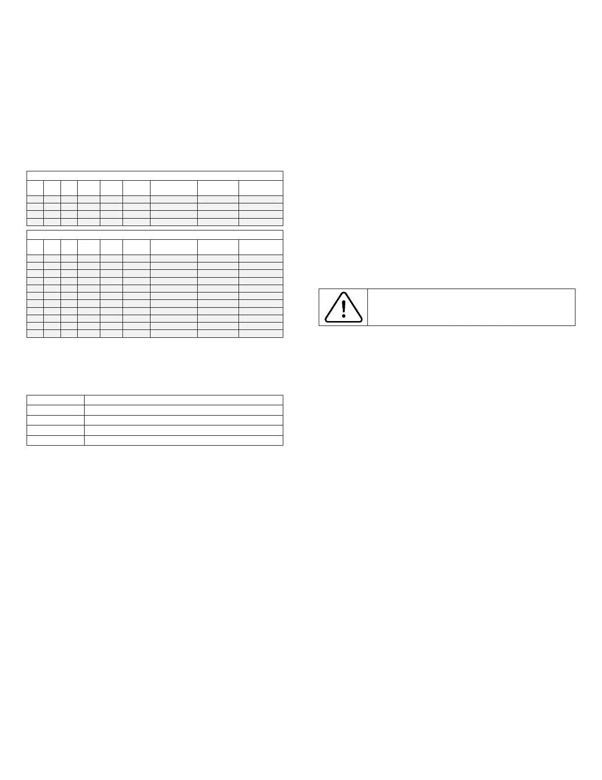
Coil Name Format Description
0 1 * * * AutoFlag Manual / Auto 1 = Auto
1 1 * * * TmRModeFlag Timer On/Off 1 = On
2 1 * * * TempModeFlag Temp On/Off 1 = On
3 1
* CommEnableFlag Comm On/Off 1 = On
Register Name Format Units
0 1 int16 * * OnTime Seconds
1 1 int16 * * OffTime Seconds
2 1 int16 * * TempSP Signed Int 8 bit Deg F
3 2 float * * ModQuarts_Day IEEE format 0.5 Qt Increments
7 1 int8 * Temperature Signed Int 8 Bit Deg F
10 1 int8 * ModMotorSize Revolutions/Min
11 2 float * ModVoltage IEEE Format VDC
13 2 int32
* ModVerNumber YYMMDD


 To Next Page
 Loading...