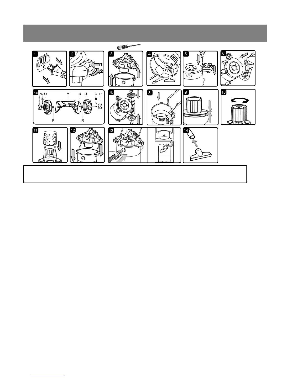
GENERAL ASSEMBLY INSTRUCTIONS
A Philips head screw driver is required.
WARNING: DO NOT PLUG IN POWER CORD TO POWER OUTLET, MAKE SURE PLUG IS
DISCONNECTED BEFORE ASSEMBLING THE WET/DRY VAC
UNPACKING YOUR WET/DRY VACUUM & GENERAL ASSEMBLY
1. Verify that the power cord is disconnected from the outlet. (fig. 1)
2. Undo the latches. (fig. 2)
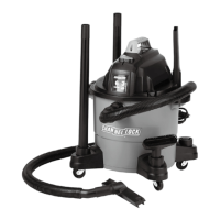
3. Lift the power head off the container. (fig. 3)
4. Remove the contents from inside the container, make sure you have all contents as listed on page 5.
(fig. 4)
5. Turn the container upside down and insert the two caster feet into the front slots on the container and
tighten with supplied screws. Verify that the casters are mounted correctly. Do not over-tighten screw.
(fig. 5)
6. Insert the rear support block (V) and secure with the supplied screws. Verify that they are mounted
correctly. Do not over-tighten screws. (fig. 6)
7. Insert the wheel shaft (S) into the rear support block (V). Insert washer (R) onto the shaft followed by
rear wheel (O). Insert the ‘R’ locking pin (Q) into the hole on the end of the shaft to lock the wheel. Snap
the hub cap (P) on to the wheel. Repeat the same steps at the other end of the shaft. (fig. 7a & 7b)
8. Insert the push/pull main handle into the handle socket mounted on the tank body. Push down until the
locking pins click in place. (fig. 8)
9. Your vacuum comes ready for dry vacuum cleaning. If cartridge filter is not installed refer to page 10 for
filter installation.(fig. 9 & 10)
10. For wet vacuum cleaning, install the supplied foam filter. (fig. 11) See page 11 for filter installation.
11. Place the power head back on the container, aligning the top section with the latches, and snap into
place. (fig. 12)
12. Insert the locking end of the hose into the vacuum port and turn to lock in to place. (fig. 13)
13. Choose the desired accessories and push onto the suction tube. (fig. 14)
6