12Ref. : CH - 1249 - A - 2
Method
• Screw the hexagonal spacers on the rear section’s 3 spacer pads, and place on each
spacer a TH M 5 x 10 screw.
• Place the lower heat-insulator (cross-shaped, 50 mm thick on black veil) under the
heat chamber taking care to jam the ends between the assembly linkages and the
chamber.
• Casing the whole of the chamber by the side insulation (50 mm thick) and tuck
its ends under the chamber (see figure 12).
• On the rear section, insert insulation (100 mm thick) on the spacers.
• NOTE : for exchangers with 8 or 9 sections, the side insulation is supplied in 2 parts
to be positioned side-by-side, the large part towards the front.
• Engage the lower rear on the three spacers and secure it by tightening the 3 screws.
• Mount both lower feet on the front section (2 screws HM 8 x 16).
• Mount the cross sections on the assembly linkages, fasten them using the counter-
nuts HM 12. The front cross-member is provided with a protection clip (110 mm long)
with a plastic collar and a NUT nut.
• Laterally secure the side rails on the cross-members using bolts HM 8 x 16 (square
hole to the front).
Front
Middle
Rear
Nb. of elements
7
300
510
514
8
300
510
684
9
300
510
854
A
C
B
6
300
854
5
300
684
4
300
514
Operation
Open the "casing" parcel
Rear spacer (50)
(see figure 15)
Body insulation blanket (33)
(see figure 12)
Lower rear (51)
Lower foot (52)
Cross-member (53)
Right side-rail (54)
Left side rail (55)
3 . 4 Operational assembly diagram (continued)
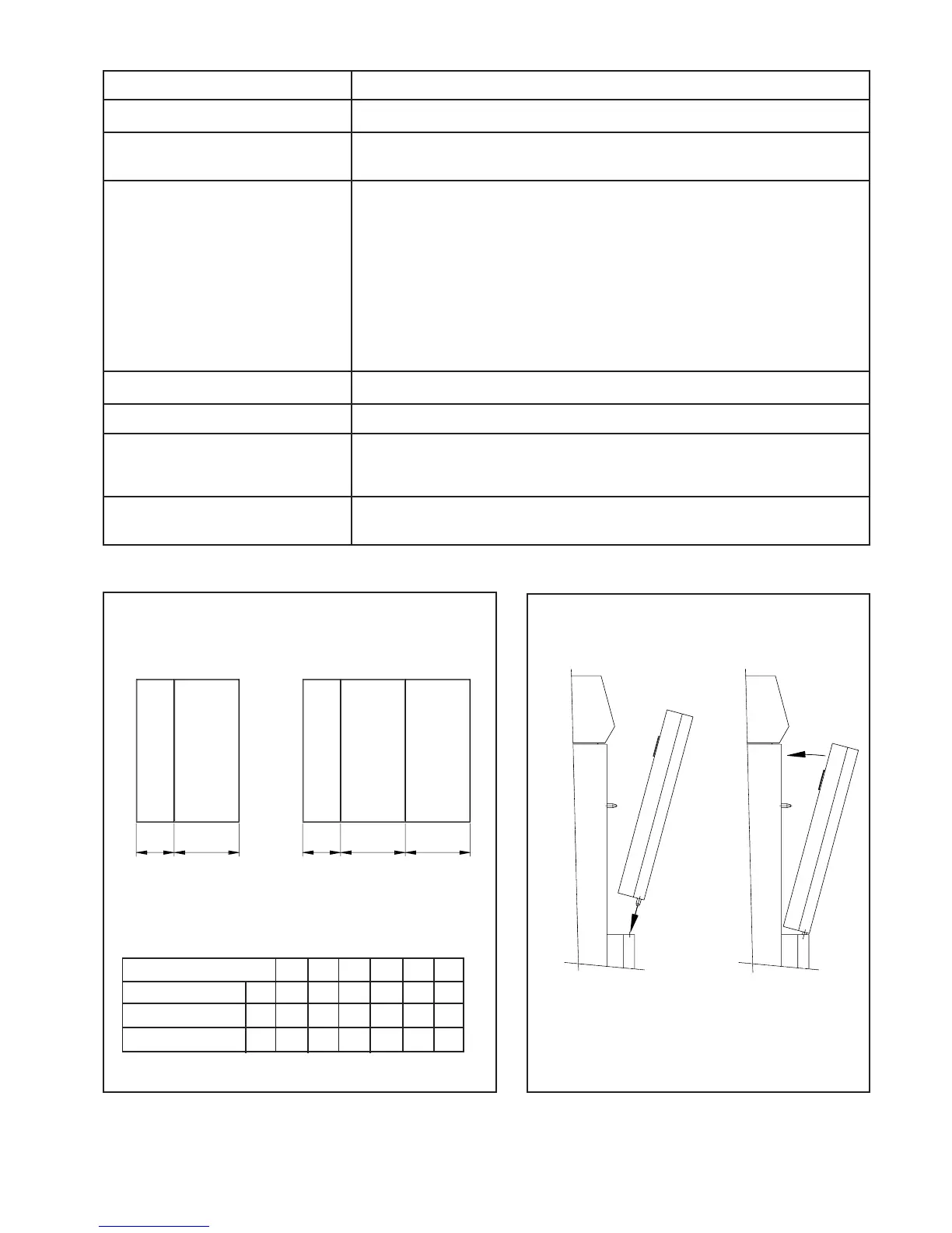
Fig. 13
Fig. 14
Rear
Front
Rear Middle
Front
A B A C B
Casing sides assembly Front casings assembly
N0220900.PLT
N0221000.PLT