5
Product Manual - Carbo-Max
®
Bulk CO
2
Systems
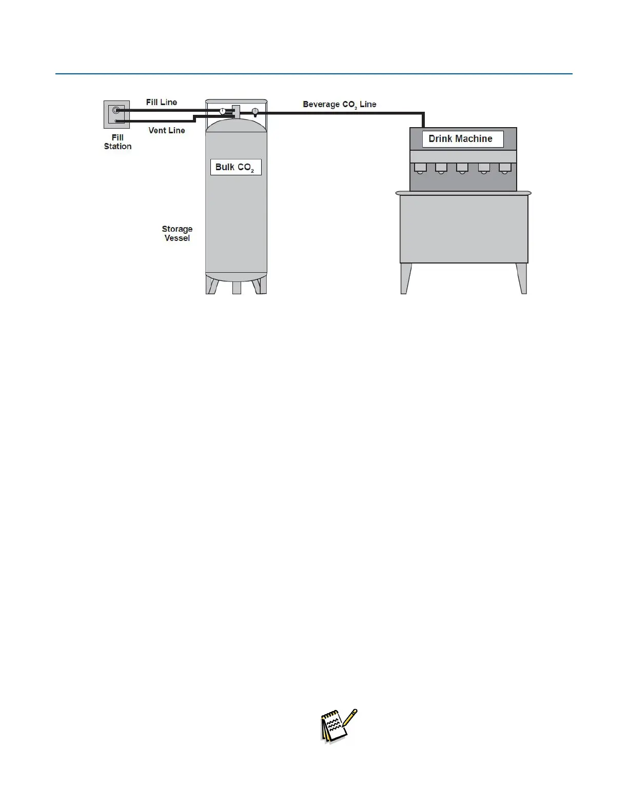
System Overview
The Bulk CO
2
Storage System is designed to provide safe,
convenient low pressure liquid storage and supply of carbon
dioxide gas for purposes including beverage carbonation,
beer dispensing, brewing, and pH control in swimming
pools. The system consists of three primary elements: the
CO
2
storage tank, a CO
2
ll box (ll station), and connecting
ll hose and vent line.
Bulk CO
2
Storage Tank
The storage tank consists of an inner tank and an outer
tank, much like a giant Thermos
®
bottle. The space between
the two tanks contains a vacuum and additional insulating
material. The vacuum and insulation minimize the entry of
unwanted heat into the liquid CO
2
stored in the inner tank.
The tank construction includes an internal vaporizer (coil)
and external plumbing conguration that combines to
maintain adequate CO
2
gas supply rates. When CO
2
gas
is needed, liquid CO
2
is drawn from the inner tank and
converted to gas. An adjustable line regulator supplies gas
to the end use point at the desired pressure. The gas use or
"nal line" regulator is normally set between 90 and 115 psi.
In accordance with ASME standard, primary and secondary
relief valves protect the tank in the event of excessive
pressure. Excess pressure is vented safely to the outside.
Fill Station
The stainless steel ll station (box) is the second major
element of the bulk CO
2
storage system. The lockable
remote ll box is permanently mounted on an outside wall. It
contains a tting for lling the storage tank at any time of the
day without entering the store. The ll box is also equipped
with a vent connection through which CO
2
gas from the
storage tank's pressure relief or Sure-Fill
™
System circuits
can be released to a safe area outside. If a tank is located
indoors and is equipped with a direct ll tting, not using a
ll box located outside, the tank pressure relief circuit must
still be vented to the outside.
Fill Hose and Vent Line
The third major element of the stationary bulk CO
2
system
is comprised of a ll hose and vent line. These two lines join
the outdoor ll box with the CO
2
storage tank.
The ll hose, constructed with FDA approved food grade
materials, is a pressure rated line that connects the brass ll
tting in the ll box with the ll circuit on the tank. The hose
is available in standard lengths equipped with connector
ttings. Common standard ll hose lengths are 5, 10, 15, 25,
and 30 feet.
The vent line is as important as any component in the bulk
CO
2
system. It connects the safety relief valves and the Sure-
Fill system on the tank to either the outdoor ll box vent
xture or to an alternative outdoor vent tube.
Note: When used indoors a CO
2
storage tank
must always be connected with a vent line
to the outdoors (see Safety section).
Introduction
 Loading...