Mega Moon™ User Manual 7 9/16/2010 4:11 PM
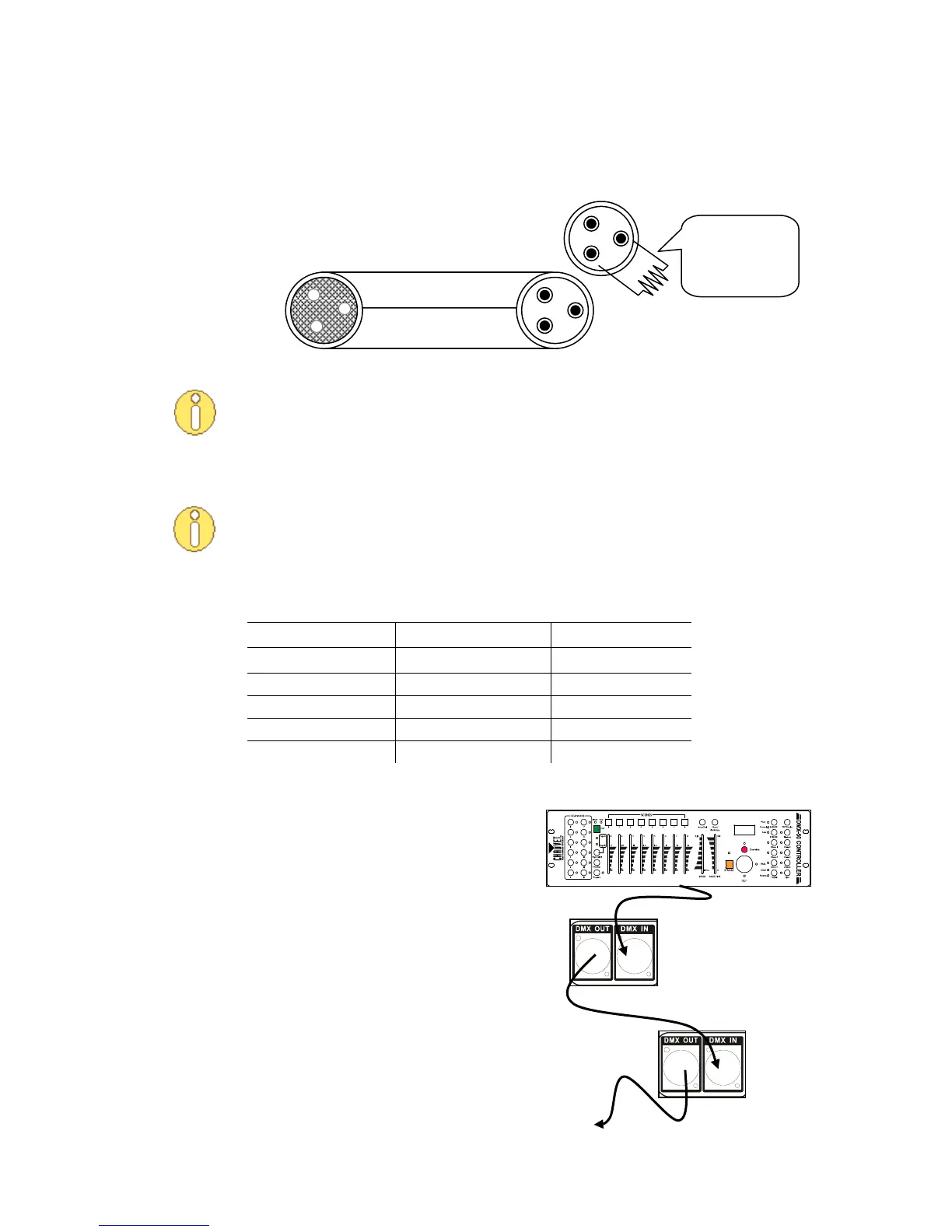
This drawing provides
a general illustration of
the DMX Input/Output
panel of a lighting
fixture.
Cable Connectors
Cabling must have a male XLR connector on one end and a female XLR connector on the other end.
Do not allow contact between the common and the fixture’s chassis ground.
Grounding the common can cause a ground loop, and your fixture may perform
erratically. Test the cables with an ohmmeter to verify correct polarity and to make
sure the pins are not grounded or shorted to each other.
3-Pin to 5-Pin Conversion Chart
If you use a controller with a 5-pin DMX output connector, you will need to use a 5-
pin to 3-pin adapter. You may use the CHAUVET Model number DMX5M, or DMX5F.
The chart below details the proper cable conversion:
3-PIN TO 5-PIN CONVERSION CHART
Setting up a DMX Serial Data Link
1. Connect the (male) 3-pin connector of the
DMX cable to the output (female) 3-pin
connector of the controller.
2. Connect the other end of the cable to the
(male) 3-pin input connector of the first
fixture
3. Connect the cable from the output of the
first fixture to the input of the second
fixture.
4. Continue connecting the other features as
indicated above.
CHAUVET Certified DMX Data Cables
Order Code Description
DMX1.5 DMX Cable 1.5 m/4.9 ft
DMX4.5 DMX Cable 4.5 m/14.8 ft
DMX10 DMX Cable 10 m/32.8 ft
120 ohm, ¼ W
resistor between
pin 2 (DMX -) and
pin 3 (DMX +) of
the last fixture.
To avoid signal transmission
problems and interference, it is
always advisable to connect a DMX
signal terminator.
DMX connector configuration