4
1. INTRODUCTION
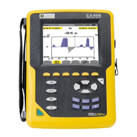
C.A 8332B and C.A 8334B are three phase power quality analysers which are compact and shock-resistant. Their ergonomic
design and the simplicity of their user interface make their use pleasant and intuitive.
They not only enable the user to obtain an instant image of a network’s principal characteristics but also to monitor their variation
over a period of time. Their multi-task measurement system simultaneously handles all the measurement functions of the various
magnitudes, detection, continuous recording: and their display without any constraints.
They are intended for the technicians and engineers of the test and maintenance teams working in industry and the administration,
for measurements, enabling them to carry out checks and diagnostic work on single phase, two phase or three phase low voltage
networks.
The principal measurements made are:
- Measurement of AC rms voltages up to 480V (phase-to-neutral) or 960V (phase-to-phase) for two-wire, three-wire or four-wire networks.
- Measurement of alternating RMS currents up to 6500A rms.
- Measurement of the frequency of 50Hz, 60Hz (10Hz to 70Hz) networks.
- Calculation of neutral current by vector summing of phase current for star configurations.
- Calculation of peak factors for currents and voltages.
- Calculation of the K factor for currents (transformers).
- Calculation of short-term flicker for voltages.
- Calculation of the phase unbalance for voltage and current (three-phase networks only).
- Measurement of harmonic angles and rates (with respect to fundamental value) for voltage, current or power (C.A 8334B only),
up to level 50. Calculation of overall harmonic distortion factors.
- Measurement of active, reactive and apparent power per phase and their aggregate.
Calculation of the power, shift and tangent factor .
Total amount of energy generated and received from a moment chosen by the operator.
- Monitoring of the average value of any parameter, calculated over a period running from 1 sec to 2 hours. Storage of values
over an unlimited period in the instrument memory.
- Recording, time stamping and characterisation of disturbance: Swells, dips and interruptions, overrun of power and harmonic
thresholds...
- Detection of transients and recording of the associated waveforms (C.A 8334B only).
2. PRESENTATION
2.1 Unit (see § 9. Appendix)
➀ Display on a LCD colour screen with graphic representation of network parameters in the mode chosen using the keys ➄
(see § 2.2).
➁ 6 variable function keys to modify the current display mode
➂ 4 keys which allow the user to:
access the instrument configuration parameters (see § 3.1)
memorise the current screen and access screens already stored in the memory
print the measurement results on an external printer (see “To order” paragraph)
obtain assistance on the current display mode functions in the language chosen by the user
➃ ON / OFF key
➄ Keys for choosing the display mode at any time:
Transients: display of waveforms, motor startup current (Inrush) and interruption (C.A 8334B only).
Harmonics: - representation of the harmonic ratios of voltage, current and power (C.A 8334B only), order by
order,
- determination of harmonic current produced by non-linear loads,
- analysis of the problems caused by harmonics according to their order (heating of neutrals,
conductors and motors, etc.) (C.A 8334B only)
Waveforms : representation of voltage and current waveforms or vector representation (Fresnel diagram) used for:
- the identification of signal distortion signatures,
- the display of amplitude and phase unbalance for voltage and current
- the checking of connections in the correct phase order
 Loading...