SKU 67537 For technical questions, please call 1-800-444-3353. Page 9
Accessory
(Scraper)
Spindle
(3)
Figure 3
Flange (2)
Accessory
(Cutter Blade)
Spindle (3)
Screw (1)
To install an Accessory:
Unthread the Screw (1), turning it a.
counter clockwise, and remove the
Screw and the Flange (2) from the
Spindle (3).
b.
with the four tabs on the Spindle.
Note: When attaching the Cutter Blade or
the Scraper, orient the accessory as
shown above so the Screw (1) will be
out of the way when working.
Place the cup side of the Flange c.
over the accessory and tighten the
Screw into the spindle using the pro-
Note:
Pad to the tool, then align a Sheet of
Sand paper over the pad and press
into place.
Note: Accessories may be mounted at
angles up to 90° left or right. The Ac-
cessory should not turn when mount-
ed on the Spindle (3). If it can turn,
reposition it so that four of the holes
on the Accessory line up with the four
tabs on the Spindle, then tighten the
Screw (1) securely.
Note:
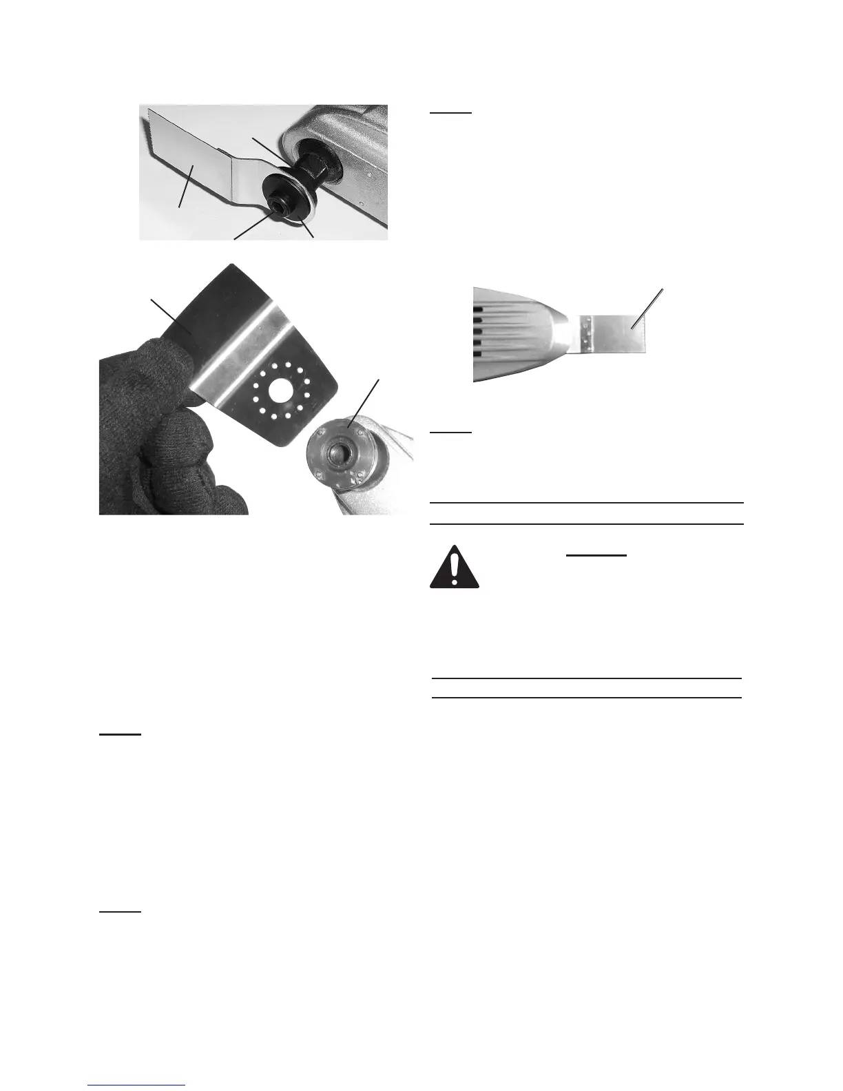
Cutter Blade Accessory
Figure 4
The long Cutter Blade should only
be used in the straight ahead position
as shown above.
OPERATING INSTRUCTIONS
Read the ENTIRE IMPORTANT
SAFETY INFORMATION
section at the beginning of this
manual including all text under
subheadings therein before set
up or use of this product.
Work Piece and Work Area Set Up
Designate a work area that is clean 1.
and well-lit. The work area must not
allow access by children or pets to
prevent distraction and injury.
Route the Power Cord (37) along 2.
a safe path to reach the work area
without creating a tripping hazard
or exposing the Power Cord to pos-
sible damage. The Power Cord must
reach the work area with enough
extra length to allow free movement
while working.