E4
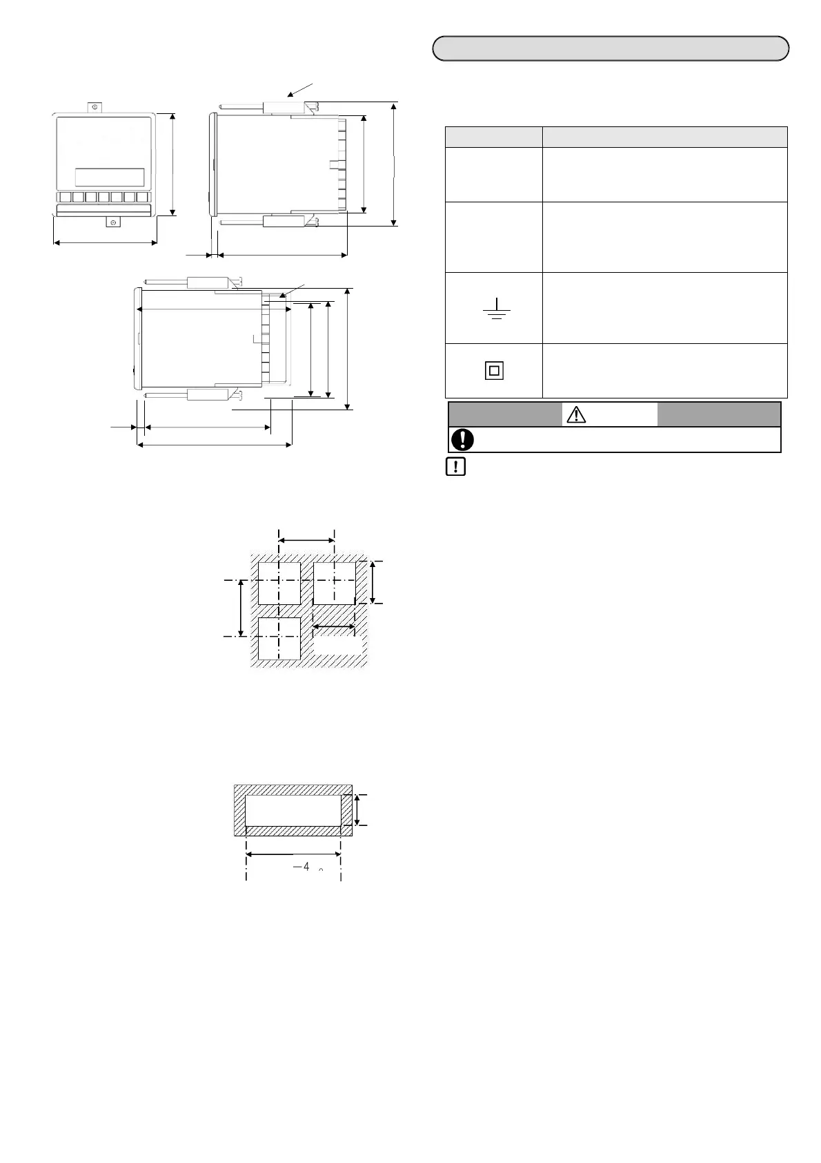
External Dimensions
KP1000 / KP2000 / KP3000 Unit : mm
Panel cutout and mounting dimensions
Usual mounting method
(1) Insert the controller in panel
cutout.
(2) Fit in the attached mounting
bracket above and below and
tighten the screws with the driver
and fix it.
The tightening torque of the
screws is '0.6 to 0.8 Nm'.
(3) For IP54 panel sealing
specifications, confirm that the
gasket between product and
panels is correct.
Take care because if the gasket
drifts or if there is a gap, the
mounting is not proper and the
water proofing function does not
work.
Closed instrumentation
(1) Insert the controller in panel
cutout.
(2) Fit in the attached mounting
bracket above and below and
tighten the screws with the driver
and fix it.
The tightening torque of the
screws is '0.6 to 0.8 Nm'.
(3) At the time of closed
instrumentation, in the product of
IP54 panel sealing specifications,
as the gasket functionality
between the product and the
panel is lost, water proofing
functionality does not work.
Step 2. Wiring
Symbol mark
The following symbol marks are used in this product itself and in this
instruction manual hence understand the meaning of these symbol
marks properly.
Label Meaning
If there is a possibility of death or severe
injuries then it explains the precautions to avoid
that possibility.
If there is a possibility of small injuries or a
possibility of the controller or its nearby devices
getting damaged then it explains the
precautions to avoid those possibilities.
It is a symbol for ground terminal.
Connect the ground terminal to the ground
terminal of the equipment. It is not a protective
conductor terminal.
Indicate the device which entire outline is
protected by double insulation or reinforced
insulation.
Precautions during wiring
• Wiring operation should be done by professional
Wiring should be done by a person having actual experience and
basic knowledge of instrumentation.
• Mount the terminal cover
In order to ensure safety, after the wiring is done, take measures so
as to prevent direct contact with the terminal of the product.
Exclusive terminal cover of the instrument is available as accessory
(Sold separately).
• Keep away from strong power circuit and noise sources
In order to prevent adverse effect due to noise, do not place the
instrument near a device from which noise is generated (magnet
relay, motor, thyristor regulator, inverter etc.). Also avoid passing the
wiring of the instrument and that of noise generating devices through
the same duct. Always keep the wiring away from each other. Take
the necessary countermeasures against noise.
• Effect on measured values
If there is a possibility that the measured values are affected by the
above noise, high voltage, etc., check that the measured values are
normal using other measurement methods. Take measures if
necessary.
• Keep away from the heat generating sources
In order to prevent adverse effect due to high temperature, do not
place the instrument near the heat generating sources. If the
instrument is kept near any heat generating source, measurement
goes wrong and finally the life of the instrument is shortened. Pay
attention to the surrounding temperature of the instrument.
Avoid places where there is wind and sudden temperature change, it
also causes an error in measurement. Take necessary measures to
avoid such surrounding environment.
• Unused terminals
Do not connect anything to the unused terminal. Instrument may get
out of order.
• Countermeasures against erroneous output at the power ON
When power is ON, sometimes the output related signal may be
momentarily output when the instrument is starting normally.
Take necessary countermeasures by using an external circuit.
• About the devices and equipment connected to this device
Make sure that devices and equipment connected to this device
have reinforced insulation suitable for the maximum operating
voltage of this device's power supply and input/output ports.
Basics of wiring
Refer to Instruction manual (General) 4-3-2 Basics of wiring for
connection to the terminal and about power supply terminal.
WARNING
Electric shock may occur, make sure to turn OFF the power
and
erform the
anel mountin
and/or wirin
o
eration.
96
96
Mounting bracket
×
120 7
Terminal cover
88×88
91×91
115
120
7
147
0
92
92
120
120
+0.8
0
+0.8
96×N-4
0
+2
N: Number of mounted instruments
Panel cutout for closed installation
92
+0.8
Warning
Precaution
Unit : mm
Unit : mm
 Loading...