E5
■Wiring
■Power supply terminal
General power supply specifications
Terminal
number
⑨
⑩
Ⓝ
⑪
Ⓛ
24V power supply specification
Terminal
number
For 24V DC For 24V AC
⑨
⑩
Ⓝ
⑪
Ⓛ
■Input terminal (Excluding KP3000)
Terminal
number
Thermocouple
Voltage mV
Voltage V
(Range No.35)
(Range No.37)
Current mA
(Range No.36)
①
②
③
④
⑤
Terminal
number
Resistance
thermometer
(3-wire)
Resistance
thermometer
(4-wire)
①
Ⓐ
②
Ⓐ Ⓐ
③
Ⓑ Ⓑ
④
Ⓑ Ⓑ
⑤
Note) Do the wiring only for the specified terminals.
Note) For current mA, short circuit ③ and ⑤.
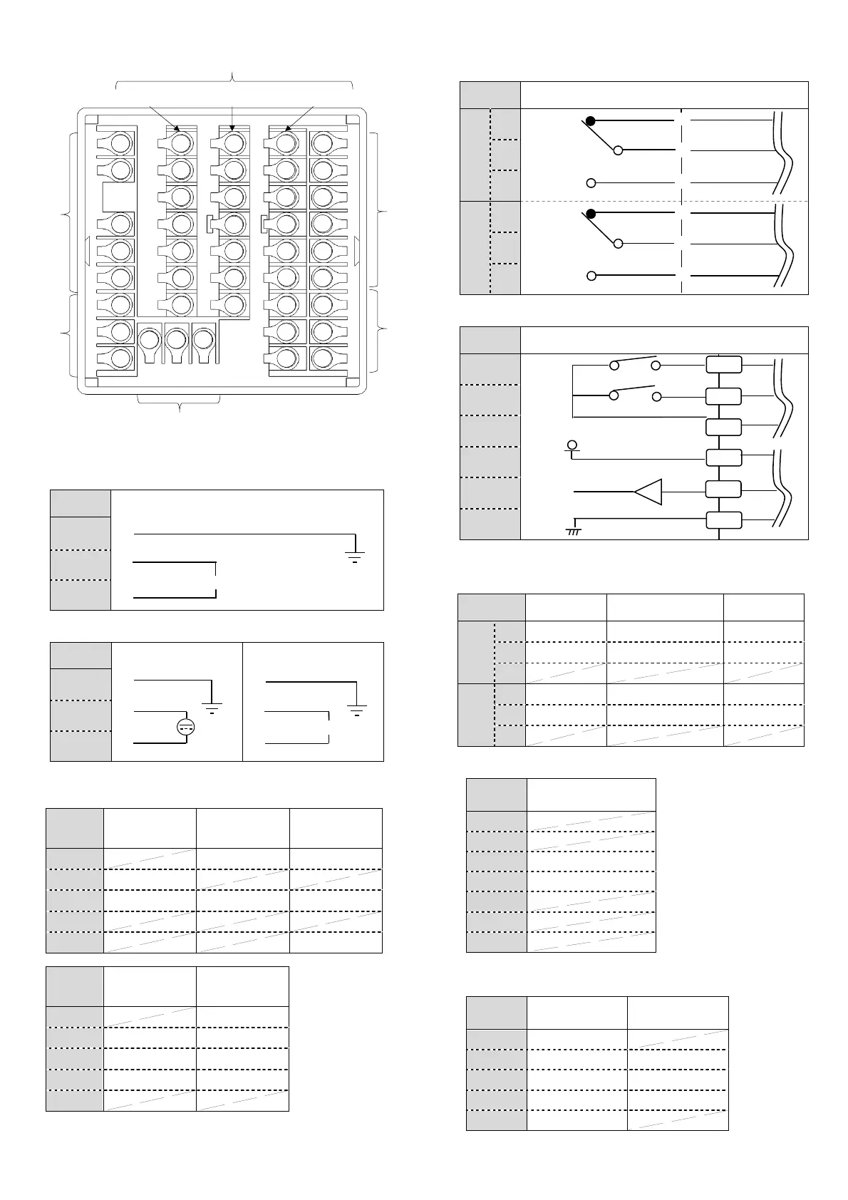
■Output terminal
ON-OFF pulse type (Excluding KP3000)
Terminal
number
Internal circuit
Output1
N.C.
Ⓗ
COM.
Ⓒ
N.O.
Ⓛ
Output2
N.C.
Ⓗ
COM.
Ⓒ
N.O.
Ⓛ
ON-OFF servo type
(Excluding KP3000)
Terminal
number
Internal circuit
CLOSE
M3
OPEN
M2
COM.
M1
OPEN
R1
COM.
RC
CLOSE
R2
Note) On open loop method (option), terminal number , , are not used.
Current output type, SSR drive pulse type, Voltage output type
(Excluding KP3000)
Terminal
number
Current
output type
SSR drive pulse
type
Voltage
output type
Output1
Output2
(For KP3000)When output signal is analog output
Terminal
number
Current / Voltage
output type
⑲
⑳
When output signal is analog output, zone 2 cannot be used as option.
(For KP3000)When output signal is digital output
Terminal
number
RS-422A
RS-485
SG
RDA SA
RDB SB
SDA SG
SDB
When output signal is digital output, external signal input and communication 2
port of zone 3 cannot be used as option.
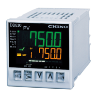
1
2
3
4
5
6
7
8
In
ut terminal
Option terminal
Zone1
43
9
10
11
12
13
14
15
16
17
18
19
20
21
22
23
24
25
26
27
28
29
30
31
32
33
34
35
36
37
38
39
40
41
42
100-240VAC
(50/60Hz)
(50/60Hz)
24VAC
24VDC
Zone2 Zone3
Alarm terminal
Alarm terminal
Out
ut terminal
Ground terminal and power supply terminal
 Loading...