EasyManua.ls Logo

CHINT NA8G User Manual

CHINT NA8G
108 pages
To Next Page IconTo Next Page
Page #1 background imageLoading...
Page #1 background image
Air Circuit Breaker
Leading every step, reliable new height

Table of Contents

Question and Answer IconNeed help?

Do you have a question about the CHINT NA8G and is the answer not in the manual?

CHINT NA8G Specifications

General IconGeneral
Poles1P, 2P, 3P, 4P
Rated Voltage (Ue)230V/400V AC
Mechanical Life20000
Electrical Life10000
Trip UnitThermal-magnetic

Summary

NA8G Air Circuit Breaker

1. General Information

General information about the NA8G Air Circuit Breaker, including application scope and standard.

2. Operating Conditions

Outlines the operating conditions for the NA8G Air Circuit Breaker, including temperature, altitude, and air conditions.

3. Product Structure

Body Structure

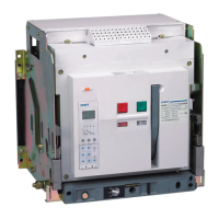
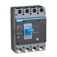
Illustrates and labels the main components of the circuit breaker's body structure.

Drawout Structure

Connection Status and Installation

Draw-out Installation Steps

Provides step-by-step instructions for installing the draw-out type circuit breaker.

4. Main Technical Parameters

4.1 Main Technical Parameters

Details the key technical specifications and parameters for the NA8G Air Circuit Breaker.

4.2 Capacity-Reducing Usage

Explains how capacity is reduced under different conditions, focusing on temperature.

4.3 Power Loss

5.4 Recommended Busbar Installation

5. Dimensions and Connection

NA8G-1600 Draw-out Type Dimensions

Details dimensions and connection for the NA8G-1600 Draw-out type.

NA8G-1600 Fixed Type Dimensions

NA8G Mounting Hole Dimensions

NA8G-1600 Draw-out Type Hole Dimensions

Provides dimensions for the mounting hole for the NA8G-1600 Draw-out type panel.

NA8G-3200 Draw-out Type Hole Dimensions

Details the size of the hole to be drilled on the panel for NA8G-3200 Draw-out type.

NA8G-4000 Draw-out Type Dimensions

NA8G-4000 Draw-out Type - Panel Hole Dimensions

Provides dimensions for the mounting hole for the NA8G-4000 Draw-out type panel.

6. Secondary Circuit Wiring

Connection Diagram for NA8G-1600 with Standard Intelligent Controller

Wiring diagram for the secondary circuit of NA8G-1600 using a standard intelligent controller.

7. Intelligent Controller and Protective Characteristics

7.1 User Interface of the Standard Type Controller

Describes the user interface of the standard type intelligent controller, including buttons and indicators.

7.3 User Interface of the Multifunctional Controller

7.4 Default Interface and Menu Structure for Multifunctional Controller

7.4.1 Structure of the Measurement Menu

Outlines the structure of the measurement menu within the multifunctional controller.

7.6 Characteristic Parameters of Standard Intelligent Controller

Overcurrent Protection Characteristics

Presents the characteristic curves for overcurrent protection.

8. Accessories

8.1 Under-voltage Release

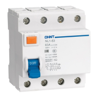
Details the under-voltage release accessory, its types, and operating characteristics.

8.2 Shunt Release

8.3 Closing Electromagnet

8.4 Motor-Driven Energy Storage Mechanism

8.7 Key Lock

9. Installation

9.1 Items to Check Before Installation

Lists items to check on the breaker panel before installation to ensure conformity with specifications.

9.4 Fixed Type Breaker Installation

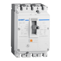
Provides instructions for installing the fixed type breaker in a distribution cabinet.

9.5 Draw-out Type Breaker Installation

Instructions for installing the draw-out type breaker and its socket.

10. Common Faults and Troubleshooting

11. Ordering Specification

Summary of NA1 Series

5 Basic Frame Sizes

Highlights that the NA1 Air Circuit Breaker includes five basic frame sizes.

1. General

1.1 Application Scope

Details the application scope of the NA1 series air circuit breaker, including voltage and current ratings.

2.6 Type Designation

NA1 Air Circuit Breaker Component Identification

NA1 Air Circuit Breaker Components

3. Structure

Draw-out Type Breaker Assembly

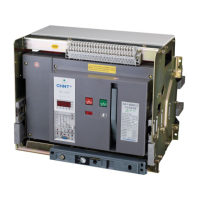
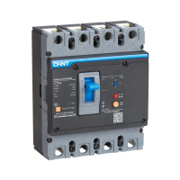
Shows the assembly of the draw-out type breaker using drawer seat and body.

Fixed Type Breaker Assembly

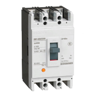
Illustrates the assembly of the fixed type breaker with mounting plates.

4. Main Technical Parameters

NA1-1000X Technical Specifications

Details the main technical parameters for the NA1-1000X model.

5. Dimensions and Connection

NA1-1000X Draw-out Type Dimensions

Provides dimensional drawings and connection details for NA1-1000X Draw-out type.

NA1-2000 Series Draw-out Type Dimensions

NA1-2000X/XN/XH Draw-out Type - Vertical Rear Connection

Dimensions for NA1-2000X/XN/XH Draw-out type with vertical rear connection.

NA1-2000 Series Fixed Type Dimensions

NA1-2000X/XN/XH Fixed Type - Panel Hole Dimensions

Details the size of the hole to be drilled on the panel for NA1-2000 Series Fixed type.

NA1-3200 Series Draw-out Type Dimensions

NA1-3200X/XN Draw-out Type - Panel Hole Dimensions

Provides dimensions for the mounting hole for the NA1-3200X/XN Draw-out type panel.

NA1-4000X Fixed Type Dimensions (3P)

NA1-4000X Draw-out Type Dimensions (3P)

NA1-6300 Series Draw-out Type Dimensions

NA1-6300X/XN (In=6300A) Draw-out Type (3P) - Panel Hole Dimensions

Provides dimensions for the mounting hole for the NA1-6300X/XN (6300A) Draw-out type panel.

6. Secondary Circuit Wiring

6.1 NA1-1000X Wiring Diagram

Provides the secondary circuit wiring diagram for the NA1-1000X model.

Secondary Circuit Wiring for NA1-2000X~6300X (Standard M Controller)

Wiring with Instantaneous Under-voltage Release

Provides wiring details for NA1-2000X~6300X with standard M controller and instantaneous UVR.

Secondary Circuit Wiring for NA1-2000X~6300X (Standard M Controller)

Wiring with Time-Delay Under-voltage Release

Wiring details for NA1-2000X~6300X with standard M controller and time-delay UVR.

7. Installation

7.1 Installation Procedures

Details the steps for installing the air circuit breaker, including unloading and fixing.

7.1.5 Partitions

Busbars

7.1.6 Busbar Connections

7.1.7 Main Circuit Cable Connection

7.1.8 Clamping

Circuit Breaker Positions

Connected Position

Describes the state where both main and control circuits are connected.

Test Position

Describes the state where the main circuit is disconnected, but control circuit is connected.

Disconnected Position

Describes the state where neither main nor control circuit is connected.

Drawout Position

Describes the state where the main body is out of the drawer seat.

7.2 Secondary Circuit Wiring

7.3 Operation

7.4 Maintenance

12. Coordination Recommendations

13. Selectivity Protection

13.1 Selective Protection between NM8 and NA1

Compares selectivity protection between NM8 and NA1 circuit breakers.

13.2 Selective Protection in NA1

14. Protection Features of Intelligent Controller

14.1 M/H and 3M/3H Intelligent Controller UI

Explains the User Interface (UI) for M/H and 3M/3H intelligent controllers.

14.2 3M/3H Controller Default Interface and Menu Structure

Describes the default interface and menu structure for the 3M/3H controller.

14.3 Explanation of M/H Controller Symbols

14.3.1 Explanation of Symbols for Reference

Provides a reference guide for symbols used in the M/H controller.

14.3.2 Operation and Display Instruction

Guides the user on operating and interpreting the display of the controller.

14.3.3 Controller Functions List

M Type Functions

Lists the functions available for the M-type controller.

H Type Functions

Lists the functions available for the H-type controller.

3M Type Functions

Lists the functions included in the 3M type controller.

3H Type Functions

Lists the functions included in the 3H type controller.

14.4 Specifications of Characteristics

14.4.1 Over-current Protection Characteristic Curve

Presents the characteristic curves for overcurrent protection.

14.4.2 Overload Long Time-Delay Protection

14.3 Short-Circuit Short-Delay Protection

14.4.4 Short-Circuit Instantaneous Protection

14.4.5 Earthing Protection

Operating Characteristics of Single-Phase Earthing Protection

15. Accessories

15.1 Under-voltage Release

Details the under-voltage release accessory, including its types and characteristics.

15.2 Shunt Release

15.3 Closing Electromagnet

15.4 Motor-Driven Energy-Storage Mechanism

15.5 Auxiliary Contact NO

15.6 Doorcase

15.9 Off Position Locking Mechanism

15.10 Key Lock

15.11 Cable Mechanical Interlock

15.12 Connecting-rod Type Mechanical Interlock

16. Maintenance and Overhaul of Circuit Breaker

Safety Precautions

Outlines essential safety precautions before performing maintenance or overhaul.

Maintenance and Overhaul Cycle

Defines the recommended maintenance and overhaul cycles based on environment.

16.2 Overhaul of Circuit Breaker

16.2.1 Connecting and Mounting Inspection

Covers inspection of connections and mounting, referring to torsional forces.

16.2.2 Insulating Property Test

Details the requirements for phase-phase and phase-earth insulation resistance tests.

16.2.3 Operating Characteristic Inspection

Describes the inspection of operating characteristics like charging, closing, and opening.

16.2.4 Inspection of Circuit Breaker Components

16.2.4.1 Face Shield Dismantling

Provides instructions for removing the face shield of the circuit breaker.

16.2.4.2 Operating Mechanism Inspection

Guides the inspection of mechanism components for damage and lubrication.

16.2.4.3 Intelligent Controller Parameter Setting

Explains parameter setting for the intelligent controller, using NA1-2000 M type as an example.

16.2.4.4 Drawer Set Inspection

16.2.4.5 Arcing Chamber Inspection

16.2.4.6 Main Contact Over-Travel Inspection

16.2.4.7 Secondary Circuit Inspection

16.3 Replacement of Accessories

16.3.1 Replacement of Fixed Accessories

Details the procedure for replacing fixed accessories like releases and electromagnets.

16.3.2 Replacement of Draw-out Accessories

17. Common Failure Causes and Solutions

17.1 Troubleshooting Logic

Presents a flowchart for troubleshooting common breaker failures.

17.2 Faulty Tripping Analysis

18. Regular Malfunctions and Solutions

Regular Malfunctions and Solutions

Breaker Cannot Store Energy

Troubleshooting for issues where the breaker cannot store energy.

Handle of Draw-out Type Breaker Issues

Addresses problems with drawing the draw-out type breaker in or out.

NA1-1000X~6300X Ordering Specification

Configuration Instructions

NA1-2000X~6300X Fundamental Configurations (Motor-driven)

Details fundamental configurations for NA1-2000X~6300X in motor-driven mode.

NA1-1000X Fundamental Configurations (Motor-driven)

Lists fundamental configurations for NA1-1000X in motor-driven mode.
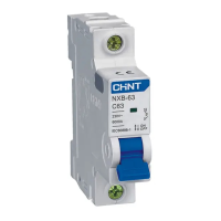
Related product manuals