C
NA1
Air Circuit Breaker
P-058
P-057
NA1
Air Circuit Breaker
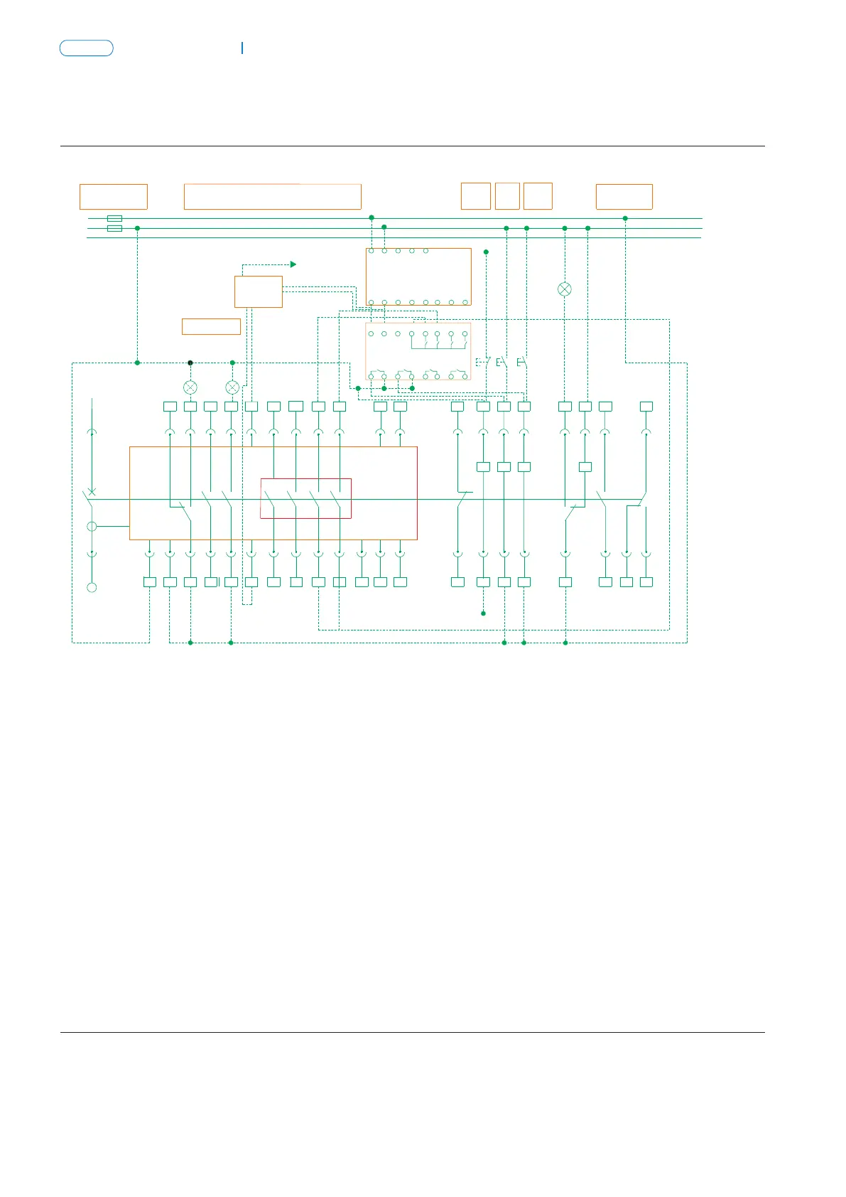
Communication type, type (H/3H)
Six pairs change-over contacts tandard type (M/3M) s
23
101 4 6
8
21
11 12 13 16
25
18
HL1
3 5
20
40
1514
39
36
97
19
27
29
31 33
22 26 30
HL2
SB2SB1
35
DF1
24
37
38
HL3
2
SB3
DF4
DF2
M
FU
FU
Power of
control circuit
▲
TA
XT
XT
34
X
F
Q
3228
DF3
17
DF6DF5
Intelligent
controller
SA
HL1: Failure indicator
HL2: Close indicator
HL3: Energy storage indicator
SB1: Under-voltage button
SB2: Shunt button
SB3: Close button
Q: Under-voltage release
F: Shunt release
X: Close release
M: Energy storage motor
DF1-DF6: Auxiliary switch
# #
1 , 2 : Auxiliary power input
# # # #
3 ,4 ,5 : Fault trip contact output(4 common
terminal,contact capacity AC230V,5A
# #
6 , 7 : to be connected with current
transformer(selective)
# #
8 ,9 : Making indicator (capacity AC400V,1A)
# #
12 ~26 : Auxiliary contact(auxiliary
contact capacity: AC230V,1A)
# #
27 ,28 : Under-voltage release(Connected to the main circuit)
# #
29 ,30 : Shunt release
# #
31 ,32 : Closing release
# #
33 ,34 :Energy storage indicator
# #
34 ,35 : Energy storage motor
# #
38 ~40 : Auxiliary contact(auxiliary
contact capacity: AC230V,1A)
Note:
, without any additional function.
Dashed is to be connected by users.
Six pairs change-over contacts
Main
circuit
Intelligent controller
Auxiliary contact
Motor-driven
energy-storage
Emergency
break
Auxiliary
contact
Motor-driven
make
Motor-driven
break
13
23
101 4 6
8
21
12
14
16
25
3
5
40
15
11
37
36
9
7
27
29
31
33
22 26 30 34
35
DF1
24
39
38
2
M
SB3SB1 SB2
▲
TA
XT
XT
19
X
F
Q
3228
DF2 DF3
18
20
17
HL1
ST-DP
Profibus-DP
Device
HL3
FU
N
PE
L1
HL2
Intelligent
controller
Fault indicator
Green
Red
SA
PSU-1
~ ~
AC 220V
+ -
DC 24V
D01
DC24V
+
RU-1
D03D02
-
DI0 D 1 I D 2 I D 3 I D 4I
D04
HL1: Failure indicator
HL2: Close indicator
HL3: Energy storage indicator
SB1: Under-voltage button
SB2: Shunt button
SB3: Close button
Q: Under-voltage release
F: Shunt release
X: Close electromagnet
M: Energy storage motor
DF1-DF3: Auxiliary switch
# #
1 , 2 : Auxiliary power input(DC24)
# # # #
3 ,4 ,5 : Fault trip contact output(4 common terminal,
contact capacity AC230V,5A
# #
6 , 7 : To be connected with current transformer(N/O auxiliary
contact, capacity AC400V, 1A,when no current transformer)
# #
8 ,9 : Making indicator(capacity AC400V,1A)
# #
10 , 11 : communication output
# #
12 , 13 : Signal alarm of load 1 output
# #
14 , 15 : Signal alarm of load 2 output
# #
16 , 17 : Making signal output
# #
18 , 19 : Closing signal output
#
20 : Communication shield ground line
# #
21 ~24 : Voltage signal input of phase N,A,B,C
(With voltage measurement);
21#~23# is a set of auxiliary switches
(Without voltage measurement)
22# common terminal,contact capacity AC230V,5A
# #
25 , 26 : Auxiliary contact (capacity:AC230V,5A)
# #
27 ,28 : Under-voltage release(Connected to the main circuit)
# #
29 ,30 : Shunt release
# #
31 ,32 : Closing electromagnet
# # #
33 ,34 ,35 : Energy storage motor
# #
36 ~40 : Auxiliary contact (capacity:AC230V,5A)
Note:
Dashed is to be connected by users.
Main circuit
Intelligent controller
Auxiliary switch
Motor-driven
break
Emergenay
break
Motor-driven
make