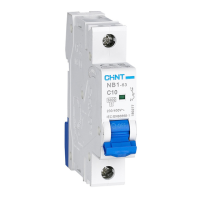
This document provides a user instruction manual for the CHINT NB1-63 Series Moulded Case Circuit Breaker.
Function Description
The NB1-63 series moulded case circuit breakers are designed for use in AC 50/60 Hz circuits with a rated voltage up to 240/415 V and a rated current up to 63A. Their primary function is to provide overload and short-circuit protection. Additionally, they can be used for infrequent switching operations of the circuit under normal operating conditions.
Important Technical Specifications
The key technical parameters for the NB1-63 Series Moulded Case Circuit Breaker are outlined as follows:
- Altitude: The device is suitable for operation at altitudes up to 2,000 meters.
- Pollution Level: It is designed for environments with a pollution level of 2.
- Installation Category: The circuit breaker falls under installation categories II and III.
- Rated Operating Voltage (Ue):
- AC 230V or 240V for 1-pole configurations (1P).
- AC 400V or 415V for 2-pole, 3-pole, and 4-pole configurations (2P, 3P, 4P).
- Rated Short-circuit Breaking Capacity (Icu): The breaking capacity is 6000A, with the NB1-63H model offering 10000A.
- Enclosure Protection Class: The device has an IP20 enclosure protection class.
- Standard: It complies with the IEC/EN 60947-2 standard.
Usage Features
Installation
The installation process involves several steps and considerations:
- Outline and Installation Dimensions: Detailed diagrams are provided showing the dimensions for 1P, 2P, 3P, and 4P versions, including overall width, height, and depth. For example, a 1P breaker has a width of 18.0-0.43 mm, a 2P is 36.0-0.62 mm, a 3P is 54.0-1.20 mm, and a 4P is 72.0-1.20 mm. The overall height is approximately 86.0-1.40 mm and the depth from the mounting surface is 49.5±0.31 mm.
- On-off Indication: The circuit breaker features a clear on-off indication. "I•ON" (Red) signifies the ON state, while "O•OFF" (Green) signifies the OFF state.
- Mounting: The device is designed for mounting on a TH35-7.5 type mounting rail. The installation procedure involves hooking the top part of the breaker onto the rail (step 1), pressing it down (step 2), and securing it with a screwdriver (step 3), then ensuring it is fully seated (step 4).
- Disassembly: Disassembly is the reverse of the installation process, involving releasing the locking mechanism and removing the breaker from the rail.
- Wiring: Only copper wires should be used for wiring. The recommended copper wire cross-sectional areas based on the rated current (In) are:
- 1-6A: 1 mm²
- 10A: 1.5 mm²
- 16, 20A: 2.5 mm²
- 25A: 4 mm²
- 32A: 6 mm²
- 40, 50A: 10 mm²
- 63A: 16 mm²
The wiring torque should be 2.0 N·m. The stripping length for wires up to 16mm² is 14mm, and for wires up to 25mm² is 15mm.
- Operation Instruction: It is recommended to carry out the closing operation by pushing the handle from the middle.
Safety Warnings
Several safety warnings are provided to ensure safe operation and installation:
- Installation in damp, condensed-phase environments with inflammable and explosive gas is strictly forbidden.
- Operating the product with wet hands is strictly prohibited.
- Touching conductive parts when the product is operating is prohibited.
- Testing the product's performance by direct contact of the hot wire against the grounding device or direct short circuit of the hot wire and neutral wire is strictly prohibited.
- The power must be switched off when the product is being installed or maintained.
- The protection features are set by the manufacturer; opening or adjusting the circuit breaker at will is not allowed.
- Wiring and installation must be done by qualified personnel and checked regularly.
- Children are prohibited from playing with the product or its package.
- Foreign objects must be prevented from falling into the product.
- Do not install the product in places where gas media can cause metal corrosion and insulation damage.
- Tighten wiring screws during installation to prevent loose or pulled-out wires. Select wires strictly according to instructions and connect them to the proper power supply and load.
- This product does not provide protection for electric shock and electricity unbalance.
Maintenance Features
Regular maintenance and troubleshooting are crucial for the circuit breaker's longevity and safe operation:
- Regular Checks: The circuit breaker should be checked regularly during operation.
- Fault Elimination: After the circuit breaker cuts off due to overload or short-circuit current, the fault must be eliminated before re-closing the circuit breaker.
Analysis and Troubleshooting of Common Faults
A table is provided for analyzing and troubleshooting common faults:
- Symptom: The handle cannot close the circuit breaker.
- Cause: Short circuit at load end. Troubleshooting: Eliminate the fault.
- Cause: Fault occurs to the operating mechanism. Troubleshooting: Replace the product.
- Cause: The rated current of the circuit breaker does not match the load current. Troubleshooting: Replace with a product of proper specifications.
- Symptom: Temperature is too high.
- Cause: The wire is loose or not properly fixed by wiring screws. Troubleshooting: Tighten the wiring screws.
- Cause: The cross-sectional area of the selected wire is too small. Troubleshooting: Replace with wire of proper specifications.
- Symptom: No power.
- Cause: The wire strip length is too short. Troubleshooting: Re-strip the wire.
- Cause: The wire is loose or not properly fixed by wiring screws. Troubleshooting: Tighten the wiring screws.
Environmental Protection
To protect the environment, the product or its parts should be disposed of according to industrial waste treatment processes. Alternatively, they should be sent to a recycling station for assortment, dismantling, and recycling in accordance with local regulations.