Do you have a question about the CHINT NM8N Series and is the answer not in the manual?
Provides essential safety guidelines for handling and installing the circuit breaker to prevent hazards.
Details the purpose, application, and general specifications of the NM8N High-voltage (HV) Series Circuit Breaker.
Explains the coding system used for NM8N series circuit breaker models, specifications, and features.
Specifies the acceptable ambient air temperature and humidity ranges for operation and storage.
Outlines requirements for installation sites, including resistance to shaking, impact, vibration, and inclination.
Defines the temperature range, ventilation, and protection requirements for product transportation and storage.
Lists necessary tools and outlines preliminary checks before installation or operation.
Emphasizes that installation, operation, repair, and maintenance must be performed by qualified personnel.
Illustrates the different operational states: LOCK, ON, OFF, and TRIP of the circuit breaker.
Provides general dimensional data and variations for different models of the NM8N series.
Presents specific overall and installation dimensions for the NM8N-250HV model with diagrams.
Presents specific overall and installation dimensions for the NM8N-400/630HV models with diagrams.
Details the required opening sizes on the front cover for NM8N 250-630 HV models as per figures and tables.
Explains the adjustable settings for over-current and short-circuit protection in thermal magnetic releases.
Provides a table detailing the setting values for thermal and magnetic protection for various models.
Specifies dimensions for front connection plates and conductors used with NM8N series circuit breakers.
Details the recommended installation steps and required torque specifications for connections.
Provides detailed specifications for terminals and connections, including size and material requirements for different models.
Details tripping characteristics for thermal magnetic protection across all NM8N models and current ranges.
Details tripping characteristics for electromagnetic protection for motor applications across all NM8N models.
Provides a table of rated working current at different temperatures and their compensation coefficients.
Lists derating coefficients for rated working current based on installation altitude.
Identifies and describes internal accessories such as auxiliary contacts and various release types.
Illustrates the wiring connections for internal accessories like auxiliary and alarm contacts.
Defines the product warranty period and lists conditions that are excluded from warranty coverage.
Provides guidance on the proper environmental protection and disposal of the product as industrial waste.
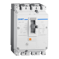
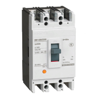
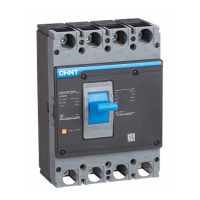
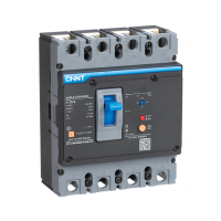
The CHNT NM8N High-voltage (HV) Series Molded Case Circuit Breaker is a robust electrical protection device designed for use in AC 50Hz/60Hz electrical systems with a maximum AC voltage of 1140V and a maximum rated current of 630A. This instruction manual details its operation, technical parameters, and installation guidelines, ensuring safe and reliable performance.
The primary function of the NM8N Series Molded Case Circuit Breaker is to provide reliable protection for electrical systems against various fault conditions. It is engineered to automatically interrupt the electrical circuit in the event of an overload, short-circuit, or under-voltage condition, thereby preventing damage to equipment and ensuring the safety of the electrical system. Additionally, it offers short-circuit protection for infrequent starting of electrical motors. This dual protection capability makes it a versatile component in industrial and commercial electrical installations. The circuit breaker is designed to make and break electrical circuits efficiently, contributing to the stability and longevity of the connected systems. Its high-voltage rating allows it to be integrated into demanding applications where robust protection is paramount.
The NM8N Series Circuit Breaker is designed for ease of use and reliable operation, though strict adherence to safety guidelines is essential. It is crucial to install the product in environments free from flammable and explosive gases, as well as wet condensation. Operation with wet hands is strictly prohibited to prevent electrical hazards. During operation, users must avoid touching any conductive parts of the product.
Installation, repair, and maintenance procedures require the power line to be completely shut off to ensure safety. The device should not be installed in locations where gas mediums could corrode metal components or damage insulation, as this could compromise its protective capabilities. To prevent dangerous accidents, all installation and fixing procedures must strictly follow the requirements outlined in this instruction manual.
The circuit breaker's thermal-magnetic release mechanism offers adjustable settings for both over-current and short-circuit protection. This adjustability allows users to fine-tune the protection characteristics to match the specific requirements of their electrical system. For instance, the long-delay current setting can be adjusted via a knob, enabling precise control over overload protection. Similarly, the instantaneous current setting for short-circuit protection can also be adjusted, providing flexibility in coordinating with other protective devices in the system. This adaptability ensures optimal protection for various load types, including power distribution circuits and motor circuits, with different tripping characteristics depending on the rated current.
The product's design includes clear indicators for its operational status, such as "ON," "OFF," "TRIP," and "Test" positions, facilitating quick visual checks and operational control. The "LOCK" position ensures that the device remains in a secure state when not in use or during maintenance. Essential tools for installation and maintenance are specified, including various sizes of screws and wrenches, to ensure proper handling and secure mounting. The overall and installation dimensions are provided in detail, including terminal cover dimensions, arc isolating plate specifications, and mounting hole patterns, which are critical for planning and executing the installation correctly. Minimum installation distances are also specified to ensure adequate clearance and prevent interference with other components.
Maintaining the NM8N Series Circuit Breaker involves periodic checks and adherence to specific environmental conditions to ensure its longevity and reliable performance. The product's operating and storage temperature range is specified from -40°C to +70°C, with an average value in 24 hours not exceeding +35°C. If the ambient temperature falls outside this range, users should consider capacity reduction or temperature compensation measures to maintain optimal performance. For instance, at maximum temperatures above +40°C, the relative humidity should not exceed 50%, while at lower temperatures, higher relative humidity is permissible, provided special measures are taken to address occasional condensation.
The installation site's altitude is also a critical factor, with a maximum recommended altitude of 2000m. For installations exceeding this altitude, an altitude derating correction factor must be applied to adjust the device's performance parameters, such as rated working current and voltage. The pollution class is specified as Class 3, and the installation category as Class III, indicating the environmental conditions the device is designed to withstand.
Transportation and storage conditions are also outlined to prevent damage. The product should be stored in a ventilated and dry place, protected from rain, snow, and direct sunlight, within a temperature range of -40°C to +80°C. Regular checks and tests are recommended to verify the technical parameters of the product. All installation, operation, repair, and maintenance tasks must be performed by professional and qualified personnel to ensure safety and proper functioning.
The manual provides detailed information on internal accessories and their installation, including auxiliary contacts (AX), alarm contacts (AL), shunt releases (SHT), and under-voltage releases (UVT). These accessories enhance the circuit breaker's functionality by providing additional control and signaling capabilities. Wiring diagrams and connection plate dimensions are included to guide proper electrical connections.
The product comes with a warranty period of 36 months from the date of production, provided it is stored and transported under normal conditions and remains intact. However, the warranty does not cover damages resulting from improper use, storage, or maintenance by the user, unauthorized disassembly or maintenance, or damages caused by force majeure.
In line with environmental protection efforts, users are advised to treat the product or its parts as industrial waste when scrapped. Alternatively, it should be sent to a recycling station for classified disassembly, recycling, and reuse in accordance with relevant national regulations, promoting responsible disposal and sustainability.
| Poles | 3P, 4P |
|---|---|
| Standard | IEC 60947-2 |
| Trip Curve | B, C, D |
| Rated Voltage (Ue) | AC 690V |
| Mounting Type | Fixed |
| Type | MCCB |
| Mechanical Life | 20000 cycles |
| Electrical Life | 10000 times |
| Rated Current (In) | 16A, 20A, 25A, 32A, 40A, 50A, 63A |