Do you have a question about the Chroma 6334 and is the answer not in the manual?
Ensure product voltage and fuse match line voltage and correct fuse is installed.
Connect protective grounding to prevent electric shock before powering on.
Do not cut off grounding wire; it prevents shock hazard.
Use only specified fuses; do not use repaired fuses or short-circuited holders.
Do not operate in presence of flammable gases or fumes.
Only qualified personnel can replace components or adjust internally.
Indicates high voltage hazard requiring reference to manual for safety.
Terminal must be connected to ground before operation to prevent shock.
Signifies a hazard; follow procedures correctly to avoid personal injury.
Signifies a hazard; follow procedures correctly to avoid product damage.
Lists technical specifications including mainframe, AC input, fuse, frequency, power, weight, and dimensions.
Details the procedure for installing load modules into the mainframe.
Explains how channel numbers are determined by module location in the mainframe.
Discusses operating temperature and space requirements for mainframe installation.
Details how to change the line voltage input setting using a switch.
Guides through pre-power on checks and self-test procedure.
Covers connecting the load to the UUT.
Provides safety warnings and connection guidelines for load wires.
Explains Vsense terminals for remote sensing and compensation.
Describes how modules can be paralleled to increase power dissipation.
Details connecting the Load via GPIB or RS-232C.
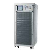
Describes the mainframe front panel, including LCD, indicators, and keypad functions.
Lists and explains over voltage, over current, over power, over temperature, and reverse voltage protections.
Guides on setting current levels, slew rates, and dynamic function periods for CC mode.
Details how to set resistance levels and slew rates for Constant Resistance mode.
Explains how to set voltage levels and response speeds for Constant Voltage mode.
| Brand | Chroma |
|---|---|
| Model | 6334 |
| Category | Power Supply |
| Language | English |