Do you have a question about the Chroma 61511 and is the answer not in the manual?
Explains the meaning of various safety symbols used in the manual to indicate hazards and precautions.
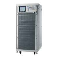
Provides a general description of the Chroma 61511/61512/61611/61612 Series AC Source.
Highlights configuration, input/output capabilities, and remote control features of the AC source.
Refers users to the User's Manual for detailed technical specifications of the AC source models.
Identifies front panel controls like display, RPG rotary, and rear panel connectors for various interfaces.
Guides users on inspecting the instrument for transit damage upon unpacking.
Provides instructions for proper placement, ventilation, and ambient temperature for the AC source.
Details input voltage/frequency ranges, max current, and Delta/Y connection methods for AC power input.
Explains how to safely and correctly connect the load to the AC source output terminals.
Details the connection of remote sense terminals for accurate load voltage monitoring and compensation.
| Type | Programmable AC Power Source |
|---|---|
| Number of Outputs | 1 |
| Display | LCD |
| Model | 61511 |
| Output Power | 1500VA |
| Output Voltage Range | 0-300VAC |
| Output Current Range | 0-12.5A |
| Frequency Range | 45 Hz ~ 500 Hz |
| Power Accuracy | ±0.5% of full scale |
| THD | <0.5% |
| Interface | GPIB, RS-232 |
| Output Voltage | 0-300VAC |
| Output Current | 0-12.5A |
| Power Rating | 1500VA |