Appendix F Calibration Procedure
20
8
2
0.2
AUTO AUTOAUTO
150
300
500
VOLTAGE
CURRENT
SHUNT
2
0.4
0.1
0.01
LH
SYSTEM
Cali
Setup
Trig /
Enter
ON
OFF
I
O
GO/NG
PASS
Shunt
Limit
Meas
RMT
FAIL
Is/Trig
PF F
E
CF
THDv
THD
V
Vpk+
Vpk-
mA
I
Ipk+
Ipk-
Is
W
PF
VA
VAR
Chroma
DIGITAL POWER METER
MODEL
66202
k
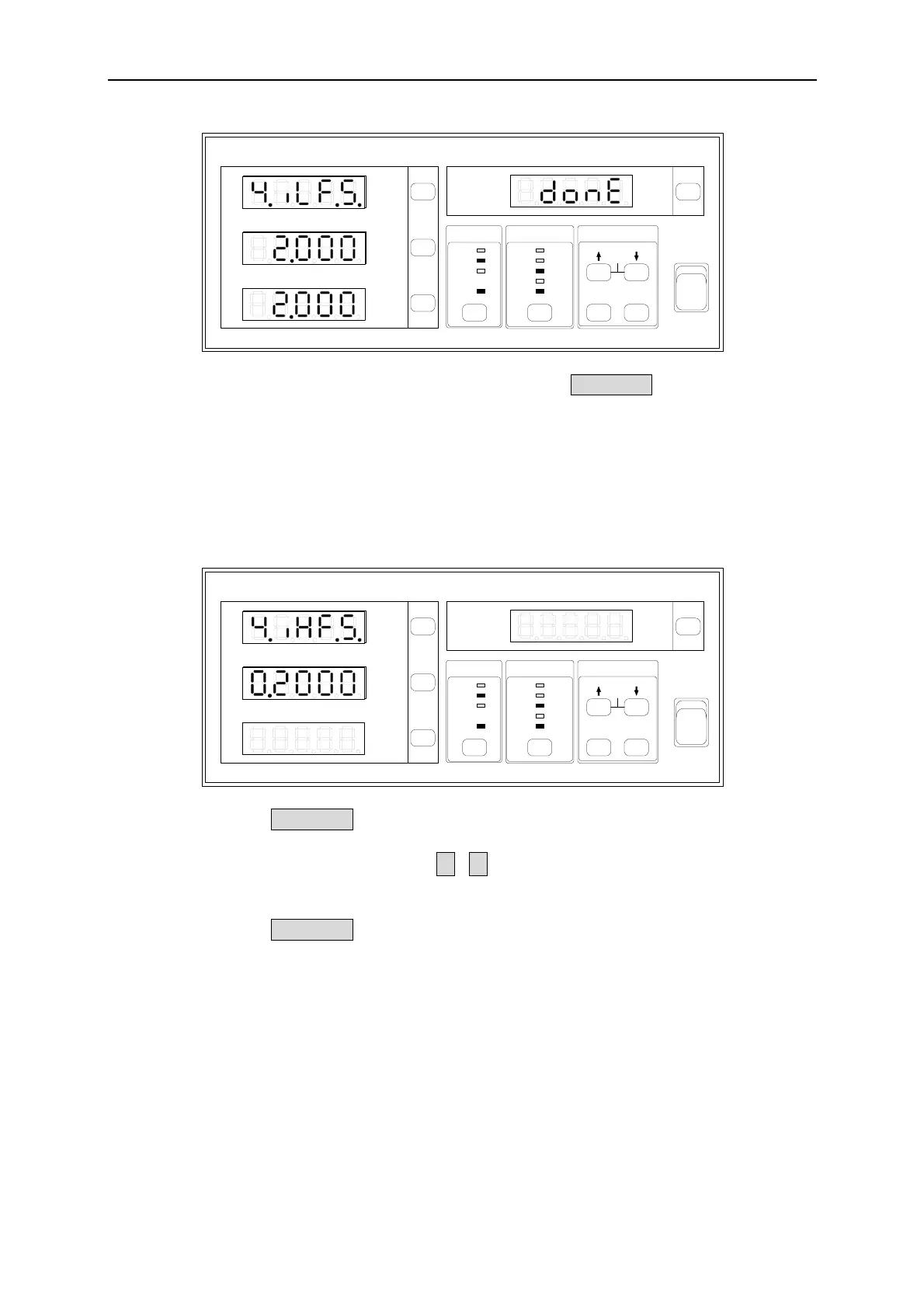
(4) Set the Fluke 5500A output to OFF and press Trig/Enter to go to the screen
for storing calibrated data.
High Current Shunt:
e. 0.2A Range Calibration:
(1) The calibration screen of 0.2A Range is shown as below (V measurement
window blinks):
20
8
2
0.2
AUTO AUTOAUTO
150
300
500
VOLTAGE
CURRENT
SHUNT
2
0.4
0.1
0.01
LH
SYSTEM
Cali
Setup
Trig /
Enter
ON
OFF
I
O
GO/NG
PASS
Shunt
Limit
Meas
RMT
FAIL
Is/Trig
PF F
E
CF
THDv
THD
V
Vpk+
Vpk-
mA
I
Ipk+
Ipk-
Is
W
PF
VA
VAR
Chroma
DIGITAL POWER METER
MODEL
66202
k
(2) Press Trig/Enter the 0.2000 in I measurement window blinks. Set the Fluke
5500A output to 150V/0.2A/60Hz and then begin to output. (To use other
voltage for calibration, use ↑, ↓ to adjust the value in I measurement
window and set the voltage in Fluke 5500A.)
(3) Press Trig/Enter the W measurement window will show the calibrated value
0.2000 (this is the reference) and the PF window will show the message
“done”. The meter will beep concurrently.
F-11