Digital Power Meter 66200 Series User’s Manual
20
8
2
0.2
AUTO AUTOAUTO
150
300
500
VOLTAGE
CURRENT
SHUNT
2
0.4
0.1
0.01
LH
SYSTEM
Cali
Setup
Trig /
Enter
ON
OFF
I
O
GO/NG
PASS
Shunt
Limit
Meas
RMT
FAIL
Is/Trig
PF F
E
CF
THDv
THD
V
Vpk+
Vpk-
mA
I
Ipk+
Ipk-
Is
W
PF
VA
VAR
Chroma
DIGITAL POWER METER MODEL
66202
1236 57109
8 12 11
4
k
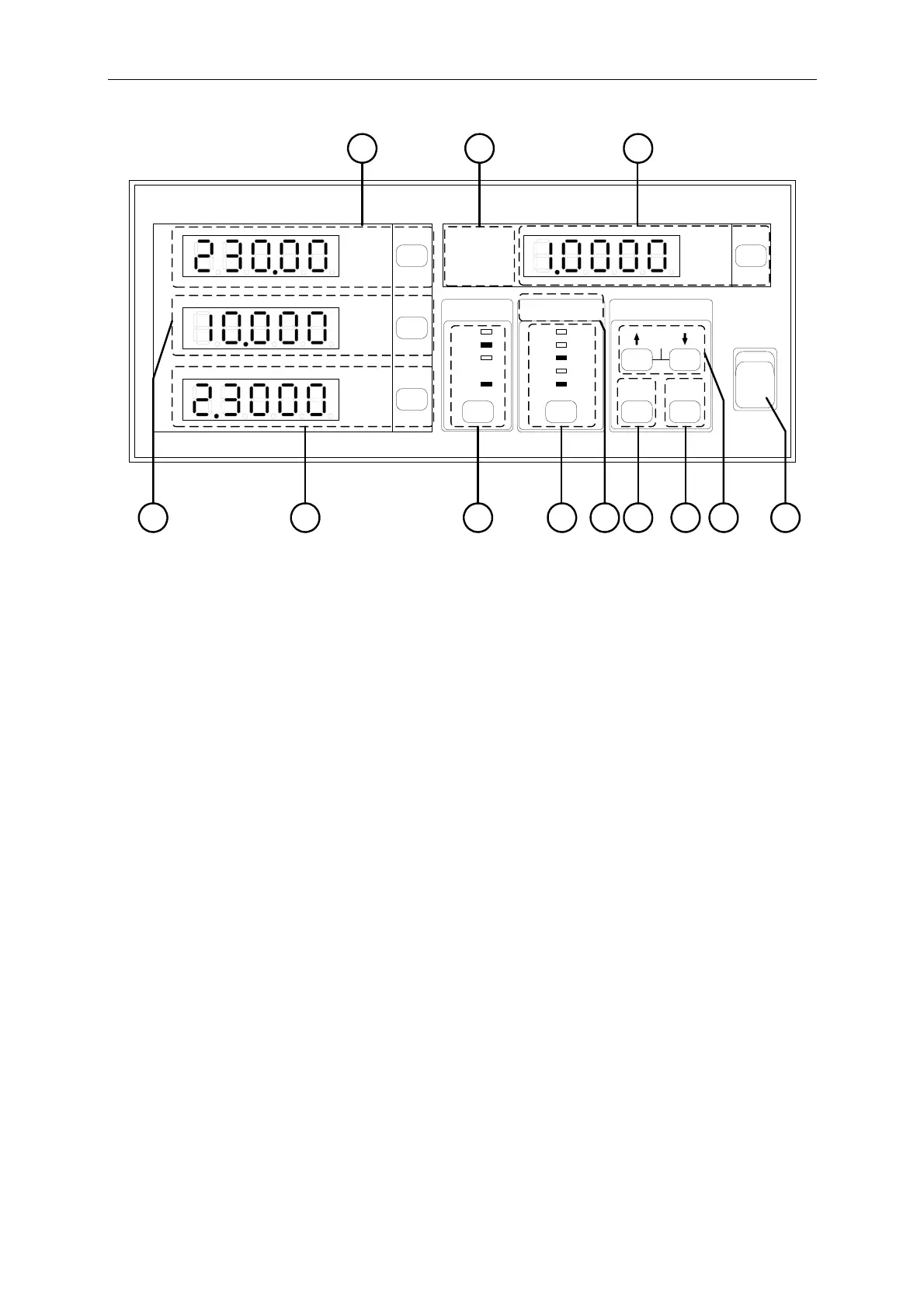
Figure 3-2 Front Panel of 66202 Digital Power Meter
(1) Power Switch
:
It is the power switch to turn the meter ON or OFF.
(2) ↑↓ Arrow Keys
:
The up and down arrow keys can be used to select the parameters
when in Setup. Press these two keys concurrently will go to
automatic calibration function.
(3) Trig/Enter
Function Key
:
It is the confirmation key for various parameters when in Setup.
(4) Setup Key :
It is the function setup key that can select various functions for
setting and the indicator above will show the selected item.
(5) Current Shunt
Indicator
:
It shows the state of Shunt module in use for current detection.
(Note 1)
(6) Current Range
Selection Key
:
It is the selection key for AUTO and specified current range. The
indicator above shows the selected range.
(Note 2)
(7) Voltage Range
Selection Key
:
It is the selection key for AUTO and specified voltage range. The
indicator above shows the selected range.
(8) Voltage
Measurement
Display
:
It is the voltage readout indicator that can switch to display V,
Vpk+ and Vpk-. The mapping indicator will be on when
selected.
(9) Current
Measurement
Display
:
It is the current readout indicator that can switch to display I,
Ipk+, Ipk- and Is (Inrush current). The mapping indicator will be
on when selected. For instance, when the mA indicator is on it
means the unit is mA.
(Note 3)
(10) Power
Measurement
Display
:
It is the power readout indicator that can switch to display W, PF,
VA and VAR. The mapping indicator will be on when selected.
(11) Special
Measurement
Display
:
It can switch to display PF, CF and F. The mapping indicator will
be on when selected.
(Note 4)
3-2