2 Chromalox 1603 User's Manual
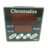
Figure 2
Wiring
6
7
8
8
9
10
8
1
2
3
4
5
INST. PWR.
T/C
RTD
+
-
OUT 2
+
-
SSR (Output Code 6 only)
MAIN RELAY (Output Code 1 only)
NO C NC
"C" "NO"
Sensor Inputs
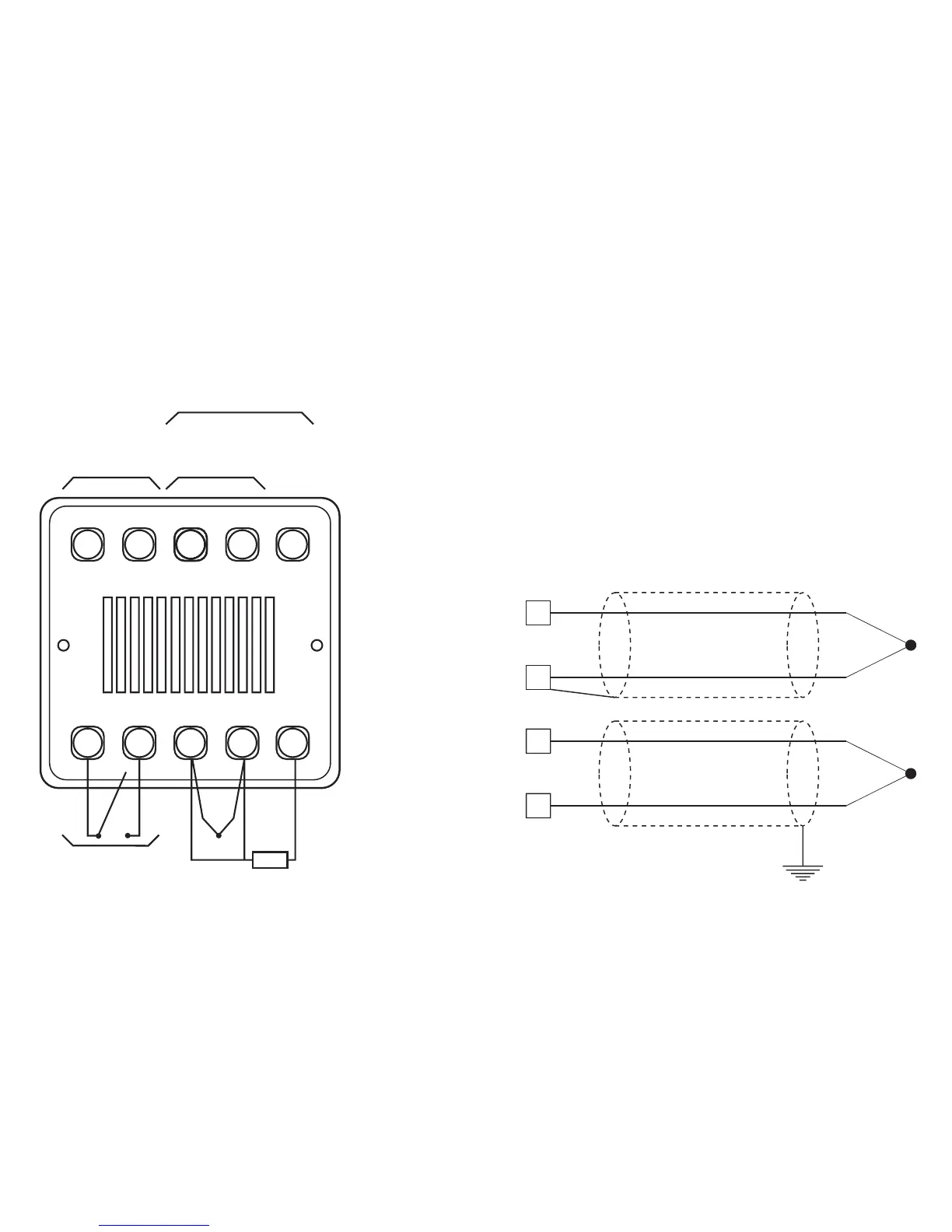
Note:
Any external components (like Zener diodes, etc.)
connected between sensor and input terminals may cause
errors in measurement due to excessive and/or not
balanced line resistance or possible leakage currents.
TC Input
Figure 3
Thermocouple Input W iring
Wiring Guidelines
3
2
+
-
3
2
+
-
 Loading...

