Do you have a question about the Chromalox 2104 and is the answer not in the manual?
Details how to identify the controller model number before installation.
Instructions for inspecting the controller upon receipt and proper unpacking procedures.
Details on locating and configuring the seven hardware switches on the controller's bottom.
Guides for setting dip switches for correct sensor type selection and input programming.
Instructions for panel cutout dimensions and physically installing the controller unit.
Best practices for system wiring, noise separation, and general connection guidelines.
Notes on proper wiring for thermocouples and RTDs, including shielding and grounding.
Details on thermocouple types, ANSI color coding, and polarity observations.
Guidance for connecting 3-wire RTDs, emphasizing leadwire compensation for accuracy.
Instructions for using 2-wire RTD inputs, including leadwire resistance compensation.
Wiring diagrams and instructions for current and voltage input configurations.
Details on connecting external switches or pushbuttons for various controller functions.
Overview of output configurations: single output control or heat/cool control.
Wiring instructions for connecting solid-state relays for output control.
Configuration for 4-20mA or 1-5 Vdc analog outputs, including jumper settings.
Connection details for 100-240 Vac and 12-24 Vac/Vdc instrument power.
Wiring diagrams for alarm/event relay outputs #3 and #4.
Wiring diagram for the Form C Relay output of Alarm/Event Output #5.
Overview of front panel pushbuttons and display functions for process monitoring.
Explains the default mode showing Process Value and Setpoint; how to change setpoint.
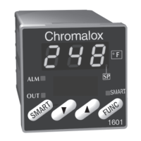
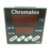
Identifies all front panel controls, LEDs, and display elements for the controller.
Details the programmable functions assignable to the AUX pushbutton.
Explains the controller's menu structure for parameter configuration and calibration.
Defines four security levels (A-D) controlling access to controller parameters.
Procedure for entering security codes on the Control PAGE to access different security levels.
Lists security codes for each level and specifies which menus can be viewed/adjusted.
Details on single output and heat/cool PID control modes, including Fuzzy Logic.
Explains PID auto-tuning for optimizing control loop performance.
Details self-tuning procedures for heat/cool control applications.
How Fuzzy Logic minimizes overshoot in PID control for improved stability.
Feature allowing setpoint to ramp to final value at powerup or during operation.
Enables manual control of the controller output from the front panel keyboard.
Provides status information only; no settings can be changed on this page.
Contains parameters for security, self-tune, PID settings, and controller type.
Sets the cooling medium type (Air, Oil, Water) or uses PID2 for cooling.
Enables or disables the remote setpoint feature.
Configures the function of the digital input or AUX pushbutton.
Assigns specific functions to the AUX pushbutton for user control.
Selects the process parameter to be transmitted via analog output.
Enables or disables the Ramp/Soak program functionality.
Allows users to set custom security codes for access levels.
Settings for sensor type, display units, setpoint limits, and calibration.
Configures decimal points and scaling for analog input and output signals.
Parameters for Output #1 cycle time, limit, and heat offset.
Parameters for Output #2 cycle time, limit, and heat offset.
Configuration of outputs #3, #4, #5 to act as timed events during ramp/soak intervals.
Enables repeating program intervals up to 9999 times for complex profiles.
Ensures soak time starts only when setpoint is reached or within differential band.
Setup for time units, standby setpoint, interval timing, and loop configuration.
How to start, hold, and stop the Ramp/Soak program using front panel controls.
Defines available alarm conditions: High, Low, Deviation, and Control Loop Protection.
Prevents false alarms during initial power-up by delaying alarm activation.
Configures relay action: normally energized/de-energized, latching/non-latching.
How to reset alarms using the RESET button or a digital input.
Parameters for Alarm #3: type, setpoints, dead band, and inhibit.
Parameters for Alarm #4: type, setpoints, dead band, and inhibit.
Parameters for Alarm #5: type, setpoints, dead band, and inhibit.
Monitors loop failures (sensor, output, load) and triggers alarms.
Using terminals 1 & 2 for remote switches to control functions like PID, Setpoint, or Ramp/Soak.
Assigning functions to the front panel AUX button for controller operation.
Details on functions like PID2 Enable, Auxiliary Setpoint, Remote Setpoint, and Output Disable.
Details functions like PID2, Auxiliary Setpoint, Remote Setpoint, and Output Disable for the AUX key.
Allows external control of setpoint via 4-20mA or 1-5 Vdc signals.
Scaling analog input/output signals and remote setpoint values.
Wiring diagrams for 2-wire 4-20mA and 1-5 Vdc transmitters.
Transmits Process Variable, Setpoint, or Output Commands via analog signal.
Scaling the analog output signal for transmission to recorders or computers.
Optional PC software for multidrop digital communication with controllers.
Instructions for RS232 and RS422/RS485 hardware configuration and wiring.
Wiring connections for digital communications using shielded serial interface cable.
Configuration of mode selection, baud rate, and address for digital communication.
Guidelines on when to recalibrate the controller, typically for periodic checks.
Key considerations and precautions before performing calibration procedures.
Procedure for calibrating sensor inputs using a simulator and the Input Page menus.
Calibrating remote setpoint inputs using a 4-20mA or 1-5 Vdc simulator.
Calibrating analog output signals using appropriate current or voltage meters.
Restores controller to factory calibration settings; used as a starting point for recalibration.
Adjusting the display/calibration offset to match other instruments or system temperatures.
Lists available automatic control modes: On/Off, Proportional, PID, and Heat/Cool.
Specifications for setpoint, deadband, proportional band, reset, and output limits.
Specifications for output offsets and cooling medium selection.
Specifications for alarm setpoints, types, relay action, deadband, and inhibit.
Details specifications for relay, SSR drive, triac, current/voltage, and optional output #5.
Specifications for sensor input types and update rate.
Technical specs for various input types: Thermocouple, RTD, current, and voltage.
Specifications for intervals, loops, event outputs, and guaranteed soak.
Specifications for digital input functionality and closure type.
Details on assignable functions, output signal, range, and accuracy for analog output.
Specifications for RS-232, RS-422/485, baud rates, protocols, and instrument power.
Physical dimensions of the controller, including panel cutout and projection.
Specifications for common mode noise, series mode noise, and RFI susceptibility.
Details effects of leadwire length and type on sensor readings for thermocouples and RTDs.
Solutions for common problems like no display, open sensor, or process not heating.
Chromalox's warranty terms, coverage, and claim procedures.
Details limitations on warranty coverage and buyer's exclusive remedies.
Procedure for returning defective parts or products, including obtaining an RA number.
Summary of security levels, codes, and view/adjust permissions.
Table listing security codes for each level and associated view/adjust access.
Detailed parameters for security lock, setpoints, self-tune, PID, and manual reset.
Setup for time units, standby setpoint, interval timing, and loop configuration.
Settings for sensor type, display units, setpoint limits, and calibration.
Configures decimal points and scaling for analog input and output signals.
Parameters for Output #1 cycle time, limit, and heat offset.
Parameters for Output #2 cycle time, limit, and heat offset.
Parameters for Alarm #3: type, setpoints, dead band, and inhibit.
Parameters for Alarm #4: type, setpoints, dead band, and inhibit.
Parameters for Alarm #5: type, setpoints, dead band, and inhibit.
Configuration of mode selection, baud rate, and address for digital communication.
Provides status information only; no settings can be changed on this page.
| Input | Thermocouple or RTD |
|---|---|
| Output | Relay, SSR Driver, or Analog Voltage/Current |
| Control Mode | On/Off, PID |
| Display | LED |
| Power Supply | 24V AC/DC, 120V AC, 240V AC |
| Dimensions | 48mm x 48mm x 78mm |
| Input Voltage | 24V AC/DC, 120V AC, 240V AC |
| Temperature Range | Depends on sensor type |
| Sensor Type | Thermocouple (J, K, T, etc.), RTD (PT100, PT1000) |