7
VOLTAGE OUTPUTS FOR SSR DRIVE
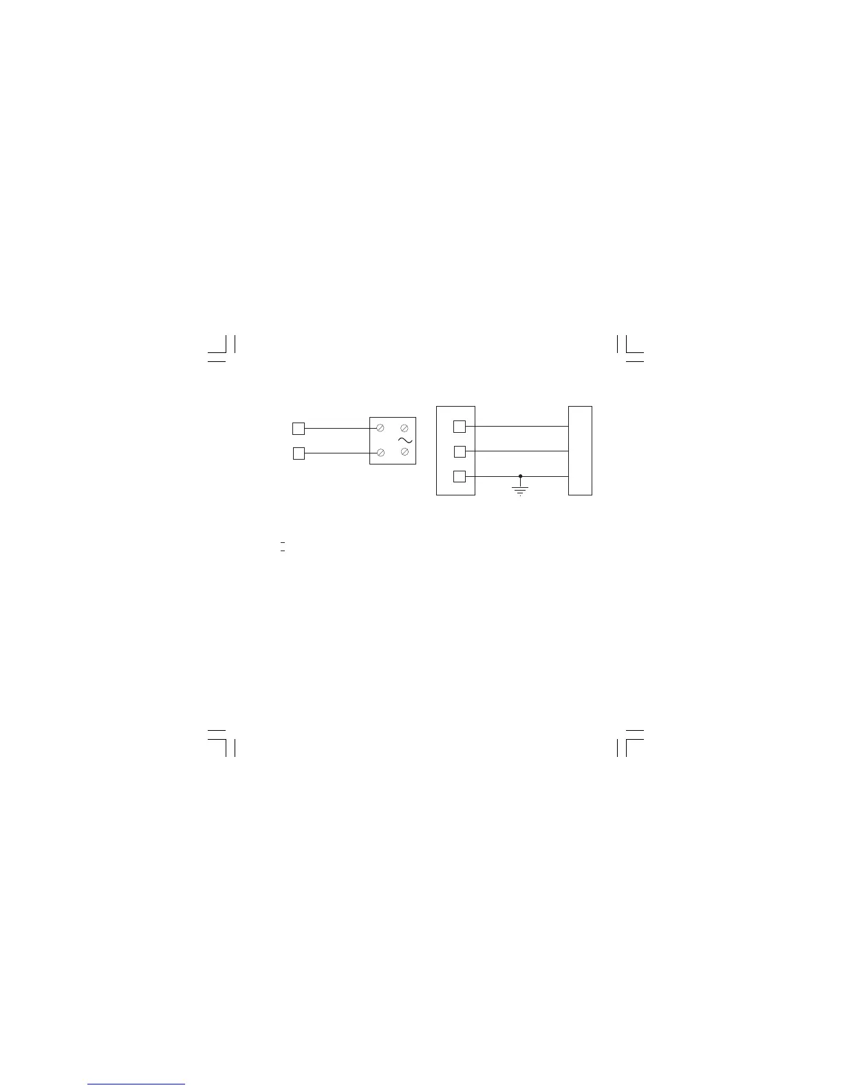
Fig. 11 SSR DRIVE OUTPUT WIRING
It is a time proportioning output.
Logic level 0: Vout < 0.5 V DC.
Logic level 1:
- 14 V
+ 20 % @ 20 mA
- 24 V
+ 20 % @ 1 mA.
Maximum current = 20 mA.
NOTE: This output is not isolated. A double or
reinforced isolation between instrument output
and power supply must be assured by the
external solid state relay.
SERIAL INTERFACE
RS-485 interface allows to connect up to 30
devices with one remote master unit.
Fig. 12 - RS-485 WIRING
The cable length must not exceed 1.5 km at 9600
BAUD.
NOTE: 1) This is an RS485 isolated interface.
2)The following report describes the
signal sense of the voltage appearing
across the interconnection cable as
defined by EIA for RS-485.
a) The ” A ” terminal of the generator shall
be negative with respect to the ” B ”
terminal for a binary 1 (MARK or OFF)
state.
b) The ” A ” terminal of the generator shall
be positive with respect to the ” B ”
terminal for a binary 0 (SPACE or ON)
12
13
COMMON
11
B'/B
B/B'
A/A'
A'/A
M
A
S
T
E
R
I
N
S
T
R
U
M
E
N
T
+
_
_
+
6
7
OUT 1
SOLID STATE
RELAY
1604-1-BC.p65 5/16/00, 10:25 AM7
 Loading...

