3
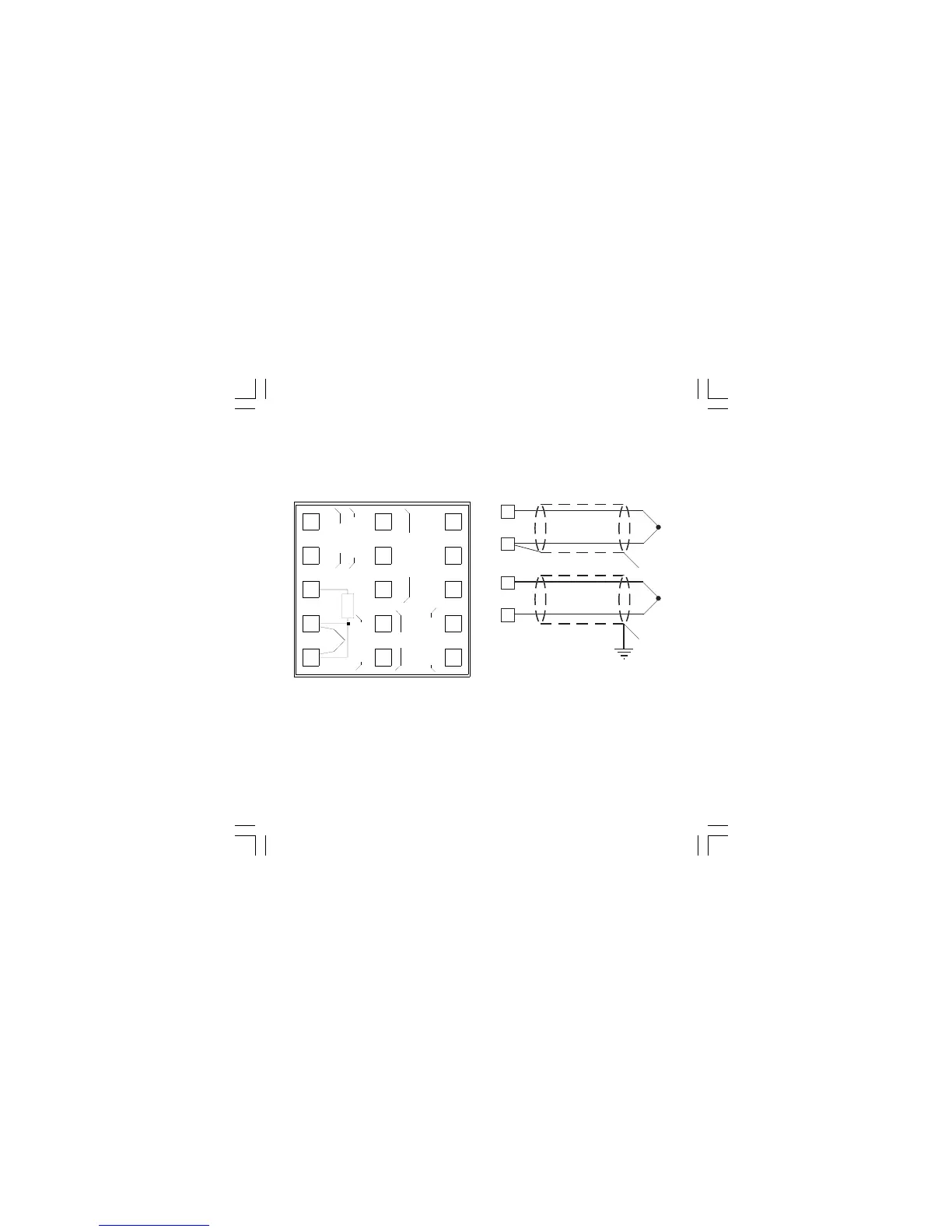
CONNECTION DIAGRAMS
Connections are to be made with the instrument
housing installed in its proper location.
Fig. 3
REAR TERMINAL BLOCK
NO
1
3
4
5
6
7
8
9
10
2
11
13
14
15
12
RS 485
NO
OUT3
SSR
OUT1
OUT2/3
LINEAR
NO
C
CPWR LINE
100/240VAC
A/A’B/B’
OUT2
IN
CT/SP-SP2
C
+
-
T/C
RTD
+
-
A) MEASURING INPUTS
NOTE: Any external component (like zener
barriers etc.) connected between sensor and
input terminals may cause errors in measurement
due to excessive and/or not balanced line
resistance or possible leakage currents.
TC INPUT
Fig. 4 THERMOCOUPLE INPUT WIRING
NOTE:
1) Don’t run input wires together with power ca-
bles.
2) For TC wiring use proper compensating cable
preferable shielded.
3) When a shielded cable is used, it should be
connected at one point only.
9
+
_
Shield
9
+
_
Shield
10
10
1604-1-BC.p65 5/16/00, 10:25 AM3
 Loading...