iiiChromalox 2104 Technical Manual
Illustrations
Figure Topic Page
2.25 Dual Output SSR/Relay Wiring............................. 17
2.26 Dual Output SSR/Triac Wiring.............................. 17
2.27 Dual Output Analog/Relay Wiring........................ 18
2.28 Dual Output Analog/Triac Wiring......................... 18
2.29 100-240 Vac Instrument Power Connections........ 19
2.30 12-24 Vac/Vdc Instrument Power Connections.... 19
2.31 Alarm/Event Outputs #3 and #4............................ 19
2.32 Alarm/Event Output #5 ......................................... 20
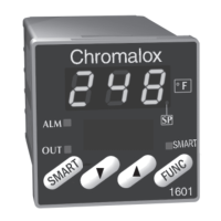
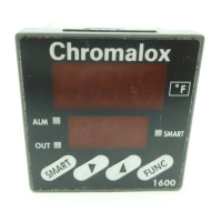
3.1 Front Panel Identification...................................... 22
3.2 PAGE/MENU Setup Structure .............................. 23
3.3 Sample of PAGE/MENU Table.............................. 25
3.4 Security Levels and PAGE/MENU Contents........ 26
3.5 Security Codes and View/Adjust Levels ................ 27
5.1 Ramp/Soak Profile.................................................. 41
5.2 Event Outputs in Ramp/Soak Profile..................... 41
5.3 Looping Intervals.................................................... 42
5.4 Guaranteed Soak .................................................... 42
6.1 CLP Alarm Connections........................................ 55
8.1 Remote Setpoint Input Signal ............................... 67
8.2 2-Wire 4-20mA Transmitter (Loop-powered)....... 68
8.3 2-Wire 4-20mA, 1-5 Vdc Transmitter (Self-powered)... 68
8.4 3-Wire 4-20mA, 1-5 Vdc Transmitter ................... 68
8.5 Analog Process Output Signal ............................... 69
8.6 Process Output Wiring ........................................... 70
9.1 RS422/RS485 Communications Switches............. 72
9.2 RS232 Wiring Connections ................................... 72
9.3 RS422A Wiring Connections (4-wire) ................. 73
9.4 RS485 Wiring Connections (2-wire)..................... 73
 Loading...