Chromalox
®
Chromalox 2110
Control Output
Wiring
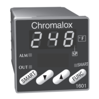
Figure 3.9
Control Output Wiring–R1 and S0
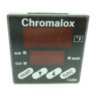
Figure 3.10
Control Output Wiring–R3
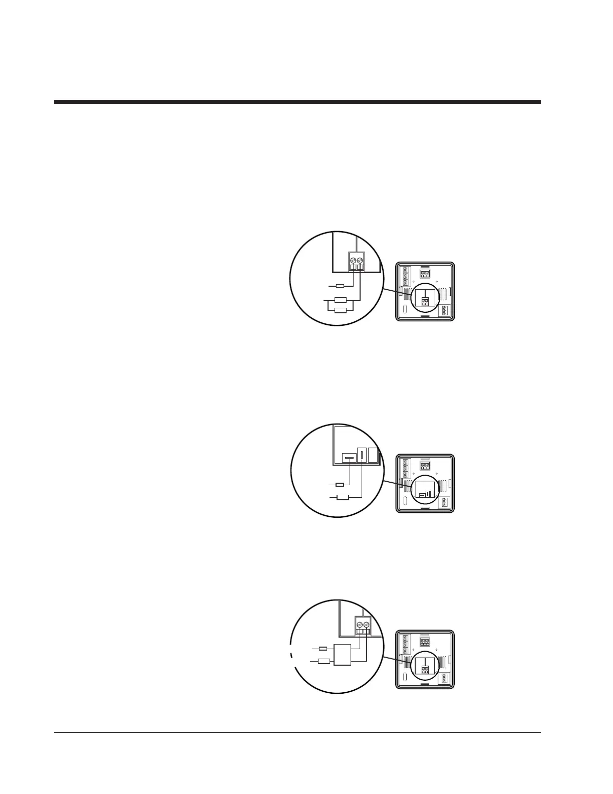
Figure 3.11
Control Output Wiring–V0
The following figures show the proper control output wiring for the
various 2110 configurations.
10
R1 (1 Amp Relay) and S0 (1 Amp, Solid State Relay)
Output Wiring
When driving a contactor coil or other inductive load, an appropriately
rated AC snubber circuit is recommended (Chromalox Part. No. 0149-
01305), as shown in Figure 3.9.
R3 (20 Amp Relay) Output Wiring
1/4” fast-on tabs are provided with the R3 output.
V0 (Solid State Relay Drive, 24Vdc, 40mA) Output Wiring
Section 3–Installation and Wiring
NC
NO
COM
Fuse
Load
Snubber
120/240
VAC
Neutral
Fuse
Load
120/240
VAC
Neutral
NC
NO
COM
NCNO
COM
NO
COM
NC
NO
COM
Fuse
Load
120/240VAC
AC Neutral
+
+
-
-
SSR
4115
 Loading...