Chromalox
®
Chromalox 2110
Module Installation
continued
18
Section 6–Replacing Output Modules
!
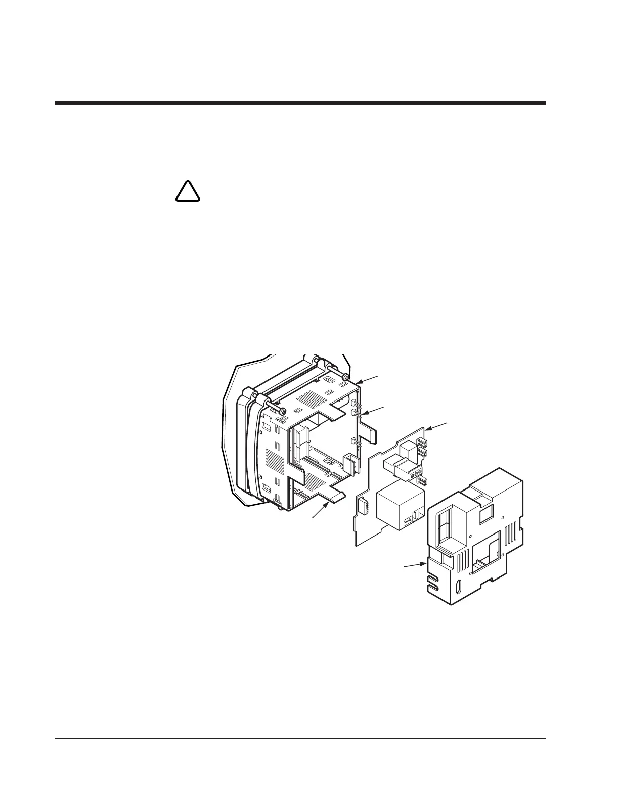
Figure 6.1
Replacing Output Module
Housing Clip
Back Cover
Controller
Pin
Module
3. Remove the back cover by lifting four housing clips on the controller.
This releases the back cover. Then pull cover straight off the controller.
4. Gently pry around the sides to loosen and remove the module. Pull
module straight out to avoid bending pin connections.
WARNING: Do not remove module by the handling components
on the module board. This could damage the module.
When removing an S2 output module (SSR with fan), a cable con-
nects the fan to the far right center of the S2 board. Gently disconnect
the cable from the connector on the output board. Do not remove
the fan from the back cover. This is a single assembly.
For the S2 output module, reconnect the fan cable to the connector on
the far right center of the module. Tuck the cable around the heatsink.
Replacement
1. Line up pins on the controller with pin connections on either side of
the module and push the new module into place.
2. Reinstall the back cover.
Auto Cycle Time
The Control Output Modules have a default cycle time of 1 second (fast
switching) or 30 seconds (slow switching) (See table on page 17). After
replacing a control output, the 2110 verifies at power up if a slow or fast
cycle time output has been installed. If an output with a different default
cycle time is installed, the 2110 will change the cycle time to the new
device’s default. If the user has changed the cycle time in configuration,
the 2110 retains this value unless an output with a different default cycle
time has been installed.

 Loading...