Installation
- 75 -
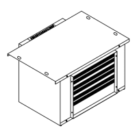
FR95-C, FR125-C/S
Refer to above figure for air exhaust mode of FR95-C and FR125-C/S. User can open
corresponding air exhaust port as required and select air exhaust strip of correct length
according to size of the port selected, round it to a ring and snap it on the port. Then connect
air duct and lead it to required position.
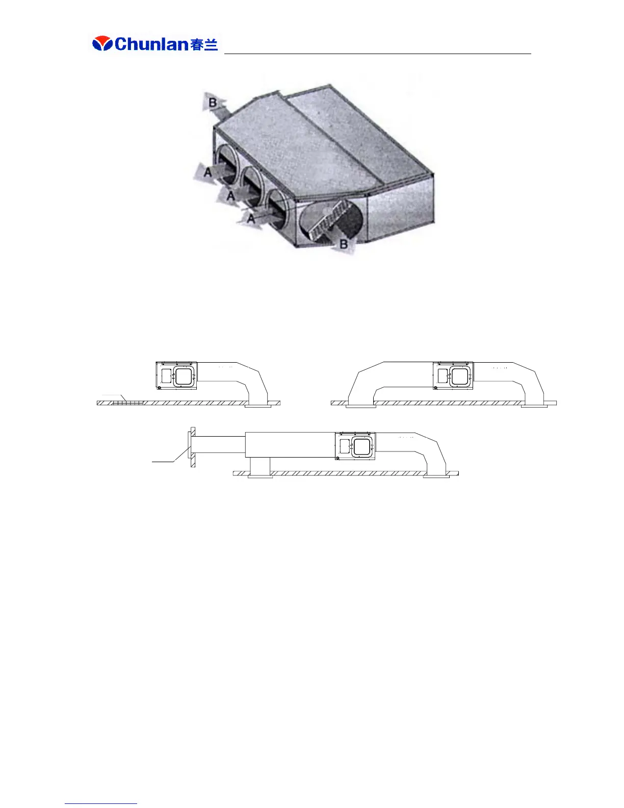
Typical installation modes of FR(D)95, FR(D)125/S, FR(D)71-B, FR(D)100-B, FR(D)180/S
and FR(D)260/S are shown above:
(1) Select reasonable installation mode according to site characteristics, user requirements and
machine performance;
(2) Cross sectional area of air duct shall meet specification. In case of noise requirement by
user, follow relevant requirements described in air duct design and noise reduction sections of
this manual;
(3) Recommended distance from main unit air return port edge to wall is above 800mm. For
FRD23-B, FRD35-B and FRD50-B, this is above 150mm;
(4) If there are many air delivery ports, to ensure even air delivery at such ports, in addition to
reducing air ducts and static pressure box installed for even flow, adjustment damper should
be provided at each branch air duct or air delivery ports with adjustment damper be selected.
(5) Air delivery and return ducts shall be fixed on prefabricated floor slab via iron support;
Air delivery duct
Return air port
Mode 1
Fresh air port
Return air port
Air delivery duct
Mode 2
Air delivery duct
Mode 3