27
7. Dip switch setting
Operate according to the following setting as necessary after refrigerant piping construction and electrical wiring
construction are nished.
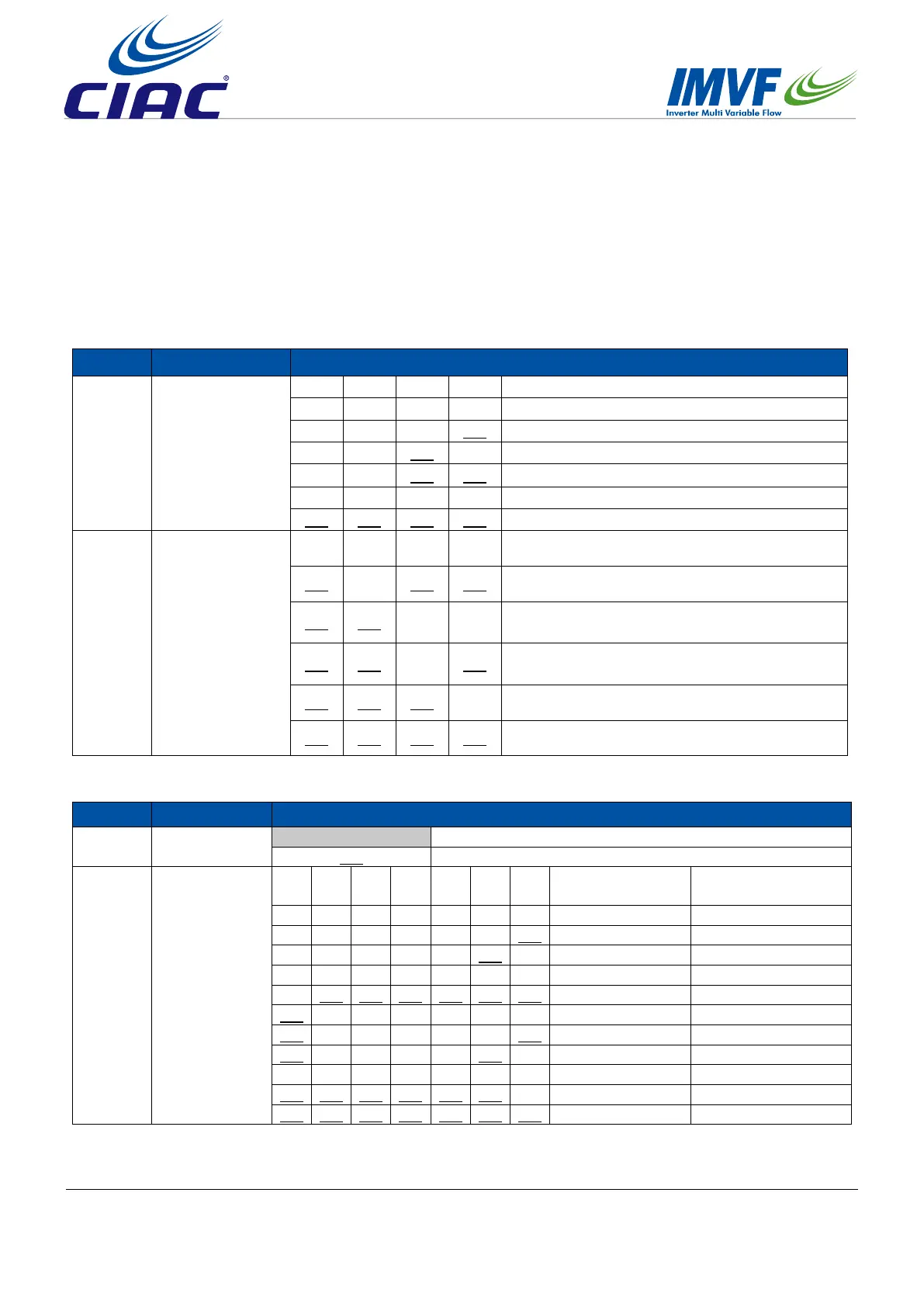
1. SW01 is used for wired control address and valve box capacity setting
SW01
Denition
Instruction
SW01_1
SW01_2
SW01_3
SW01_4
Wired control
address
[1] [2] [3] [4] Wired control address
OFF OFF OFF OFF 0# (wired control master unit) (default)
OFF OFF OFF
ON 1# (wired control slave unit)
OFF OFF
ON OFF 2# (wired control slave unit)
OFF OFF
ON ON 3# (wired control slave unit)
… … … … ……
ON ON ON ON 15# (wired control slave unit)
SW01_5
SW01_6
SW01_7
SW01_8
Valve box capacity
setting
[5] [6] [7] [8]
Indoor unit capacity
which connected to the
valve box
ON OFF ON ON
11.2kW
<
connected indoor unit's cooling
capacity ≤ 14kW
ON ON OFF OFF
14kW
<
connected indoor unit's cooling
capacity ≤ 16.8kW
ON ON OFF ON
16.8kW
<
connected indoor unit's cooling
capacity ≤ 22.4kW
ON ON ON OFF
22.4kW
<
connected indoor unit's cooling
capacity ≤ 28kW
ON ON ON ON
28kW
<
connected indoor unit's cooling
capacity ≤ 56kW
2. SW03 is used for valve box address setting
SW03 Denition Instruction
SW03_1
Address setting
method
OFF Set the address automatically
(
default
)
ON Set the address by dip switch
SW03_2
~
SW03_8
The
communication
address and
central control
address setting
[2] [3] [4] [5] [6] [7] [8]
Communication
address
Central control
address
OFF OFF OFF OFF OFF OFF OFF 0#
(
default
)
0#
(
default
)
OFF OFF OFF OFF OFF OFF
ON 1# 1#
OFF OFF OFF OFF OFF
ON OFF 2# 2#
… … … … … … … …… ……
OFF
ON ON ON ON ON ON 63# 63#
ON OFF OFF OFF OFF OFF OFF 0# 64#
ON OFF OFF OFF OFF OFF ON 1# 65#
ON OFF OFF OFF OFF ON OFF 2# 66#
… … … … … … … …… ……
ON ON ON ON ON ON OFF 62# 126#
ON ON ON ON ON ON ON 63# 127#