EN - 10 N 14.54 B
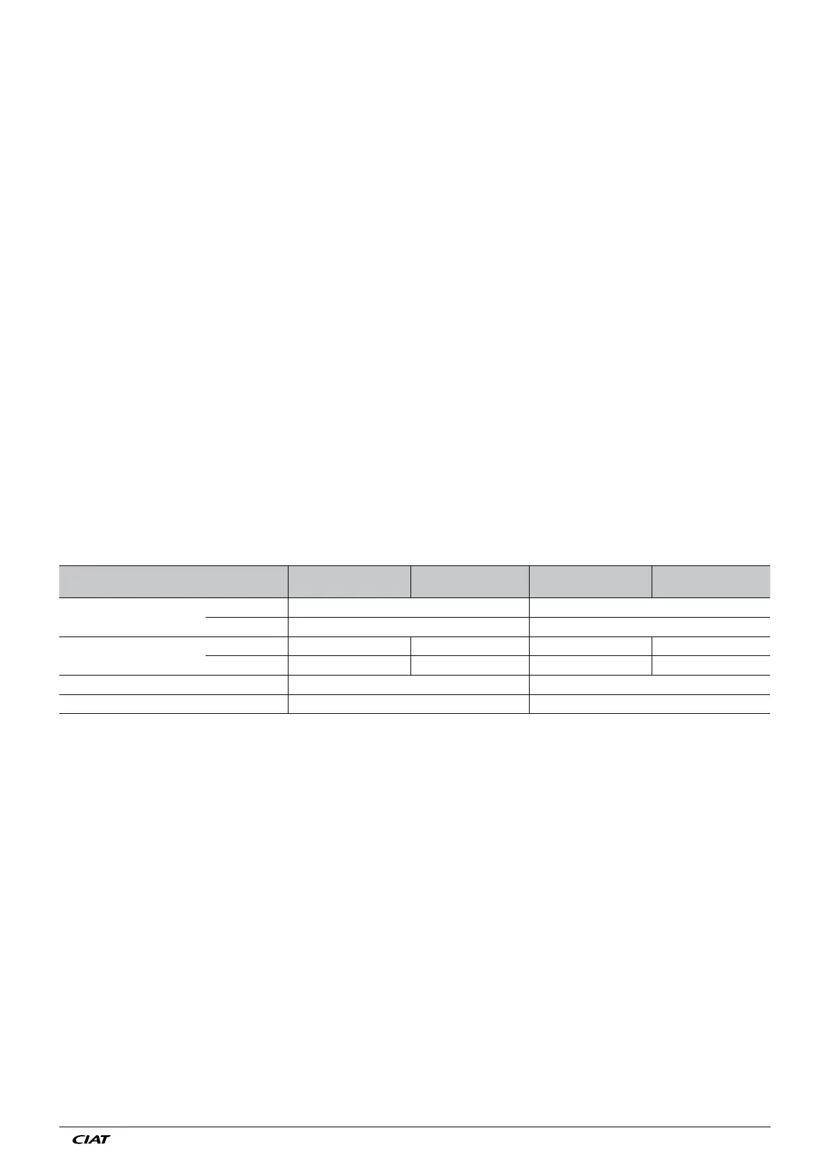
Refrigerant connection diameters
Size
DXA 59
2 x CD100
DXA 65
2 x CD120
DXA 70
2 x CD120
DXA 85
2 x CD150
Indoor unit
ø liquid 7/8" F 7/8" F
ø gas 1"1/8 F 1"3/8 F
Outdoor unit
ø liquid 7/8" M 7/8" M 7/8" M 7/8" M
ø gas 1"3/8 M 1"3/8 M 1"5/8 M 1"5/8 M
Connection tube ø liquid 7/8" 7/8"
Connection tube ø gas 1"1/8 1"3/8
A condensate drain pump option is available (see technical specifications in paragraph 12), provided that the humidifier option
has not been requested.
If the humidifier option is selected, the discharge must not drain into the unit's drain pan. To have a single discharge for both,
connect the humidifier drain downstream of the unit's drain pan.
Warning: the condensates from the humidifier can reach 100°C.
10.2 Refrigerant connections (DXA model)
Installation precautions:
The refrigerant connections between the indoor unit and the condenser (outdoor unit) must be made by qualified personnel.
Only insulated copper refrigeration pipes must be used.
This network must be designed and constructed correctly in order to ensure the entire system operates correctly.
The pipes must be sufficiently flexible to withstand fluctuations in length, expansion and contraction. The fluid line must be angled
in order to always carry the fluid to the unit.
It is important to avoid:
• Excessive refrigerant fluid loss,
• Accumulation of oil,
• Liquid ingress into the compressor, either when operating or idle,
The pipe route must:
• Not hinder, nor be hindered by, the existing installation,
• Be protected against accidental shocks,
• Be visible in its entirety, and not be encased in plaster or concrete.
• The height differences and equivalent lengths between the indoor and outdoor unit must be in accordance with the
recommendations (see Table at the end of this paragraph)
• The pipe dimensions must ensure a minimum pressure drop, and the minimum and maximum speeds must be complied with
to ensure correct circulation of the gas and movement of the oil.
• Fit oil traps every 4 metres on the vertical columns to ensure the oil is returned to the compressor.
• Check that no contamination has fallen into the tube.
• Carry out all brazing operations using a nitrogen purge.
Please see the dimensional drawing and connection diagram to locate the routing areas and connection positions.
 Loading...