EN-41 POWERCIAT LX ST/HE/XE
8.3 - Condenser location
All heat reclaim condensers are located between the air-cooled
condensers on the upper part of the chassis, supported by two
cross rails. The water inlet and outlet are on the same side.
8.4 - Condenser water connections
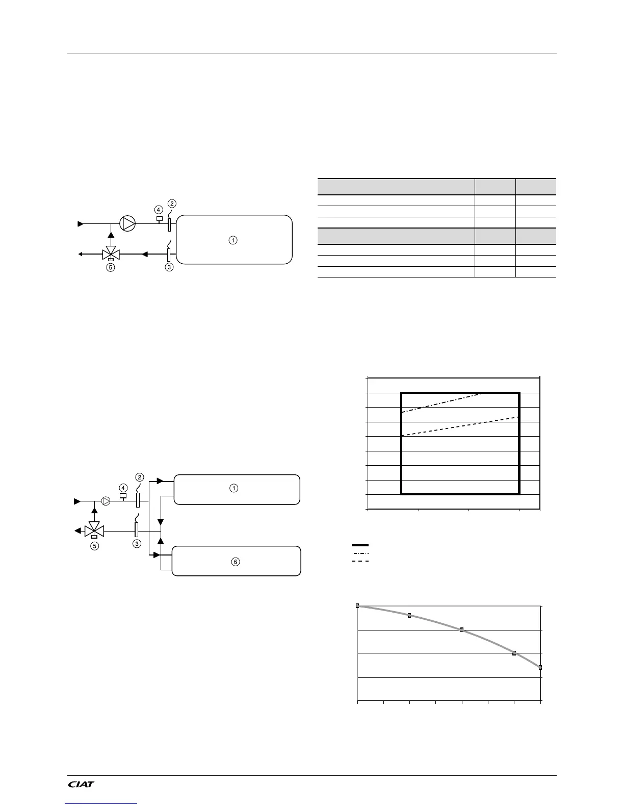
8.4.1 - Unit with one heat recovery condenser, LX 0808
to 1528
The water ow switch must be installed at the water inlet of the
installation that arrives at the heat reclaim condenser.
Key
1 Heat reclaim condenser
2 Entering water temperature sensor (supplied)
3 Leaving water temperature sensor (supplied)
4 Condenser water ow switch (supplied)
5 Three-way valve (not supplied)
8.4.2 - Unit with two heat recovery condensers, LX 1858
to 3028
The two condensers must be installed in parallel in the water system
of the installation. The water ow switch and the entering/leaving
water temperature sensors must be installed in the line that is
common to both heat reclaim circuits and as close as possible to
the condensers. A T-piece must be provided by the installer at the
water inlet and outlet of the condensers.
For units with two condensers the maximum cable length of the
temperature sensors and the ow switch (7.5 m) is designed to
allow connection to the common inlet or outlet in a radius of 4.5 m
after routing along the width of the unit.
Key
Please refer to the legend in chapter 9.4.1 opposite, noting that items 2, 3 and 4
- ow switch and sensors - are placed on the common sections.
8.4.3 - Three-way valves
It is strongly recommended to install a three-way valve in the
system (not supplied with the unit). A 0-10 V output is available
on the unit electronic board to control this valve. The valve allows
bypassing of the heat reclaim condenser entering/leaving circuit
to ensure unit operation with heat reclaim at low entering water
temperature (< 12.5 °C). It also ensures an optimal and controlled
leaving water temperature.
8.5 - Operating limits for stable operation
(no mode changeover)
8.5.1 - Cooling mode only
Please refer to the earlier chapters in this manual:
6.1 - Unit operating range
6.7 - Evaporator water ow rate
8.5.2 - Heat recovery mode
Condenser water temperature °C Minimum Maximum
Water entering temperature at start-up 12.5* 55
Water entering temperature during operation 20 55
Water leaving temperature during operation 25 60
Evaporator water temperature °C Minimum Maximum
Water entering temperature at start-up - 45
Water entering temperature during operation 6.8 21
Water leaving temperature during operation 3.3 15
* The water entering temperature at start-up must not be lower than 12.5 °C.
For installations with a lower temperature a three-way valve must be used.
NOTE: If the temperature at the evaporator is below 4 °C, a
glycol/water solution or the frost protection option must be used.
In part-load operation, the limitation of the condenser leaving
water temperature is due to the operating range of the screw
compressor. If the condenser leaving water temperature is above
the limit value given in the curves below, the unit will automatically
change over to the mode without heat recovery:
 Loading...