EN - 4
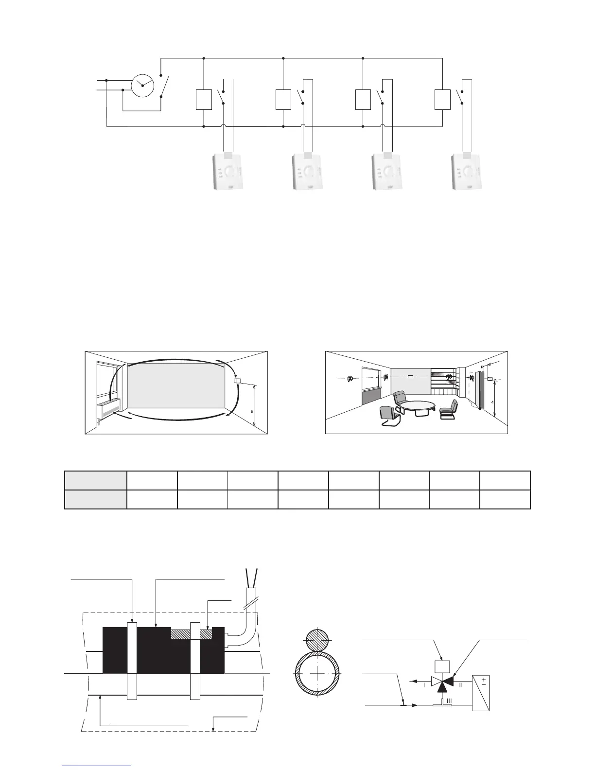
N.B.: This schematic diagram is needed for changing from comfort mode to “Eco” mode as standard (to “frost
protection” mode by on-site adjustment). It is strictly forbidden to carry out timed programming by switching off the
thermostat power supply.
N
P
K1 K2 K3 K4
CF CF CF CF
Air temperature measurement:
- A built-in thermostat regulates air temperature using a return sensor.
- A wall thermostat regulates air temperature:
n By either using an indoor environment sensor (built into the unit)
n Or by using a return sensor.
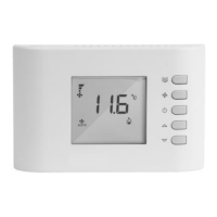
For a wall thermostat, particular attention must be paid to the position of the thermostat in the room (do not expose
it to the sun, or place it above an appliance which releases heat, place it on an inside wall). The end of the wiring conduit must be
heat insulated.
Some Values:
The return and changeover sensors have the same specifications.
Temperature
°C
5 10 15 20 25 30 35
Resistance
ohm 22,050 17,960 14,690 12,090 10,000 8,313 6,940
150 cm
150 cm
20 cm
min.
Water temperature measurement
The 2 pipe or 2 pipe + 2 wire fan coil units may have a water temperature measurement sensor (or changeover
sensor). It should be placed upline of the 4-way valve (water network side) by the installer. It is fitted to the pipe using
electrician’s clips and must be insulated
Clamping collars Sensor adapter
Sensor
Water inlet pipe
Insulation
Sensor
Valve motor
3-way valve
with built-in
bypass
(often called a
4-way valve)
Schematic diagram of connection with timer