Unit installation
N.B.!
This appliance must be installed in accordance with the connection diagram enclosed with the acknowledgement of
receipt. It must be installed in accordance with accepted engineering standards and must conform with current local
standards. In order to meet Class II requirements, the corresponding installation instructions must be observed.
Mounting:
n In 60 mm flush-mount box; cables pass through the rear
n directly on the wall using the designated holes, passing the cables through the pre-punched holes in
the base in the higher or lower section.
Electrical connection
n Open the unit
n Connect in accordance with the diagram provided, depending on the application. The connection
wires for the regulator, changeover sensor, fan, valves and electric heater have a voltage of 230V~
and must, therefore, be sized accordingly.
n Set the switches for the selected application.
N.B.: The return or changeover sensors must be wired in order to limit the length of the wires and distance them
from the power cables.
The maximum cable length with 1 thermostat and 1
appliance is 10 metres.
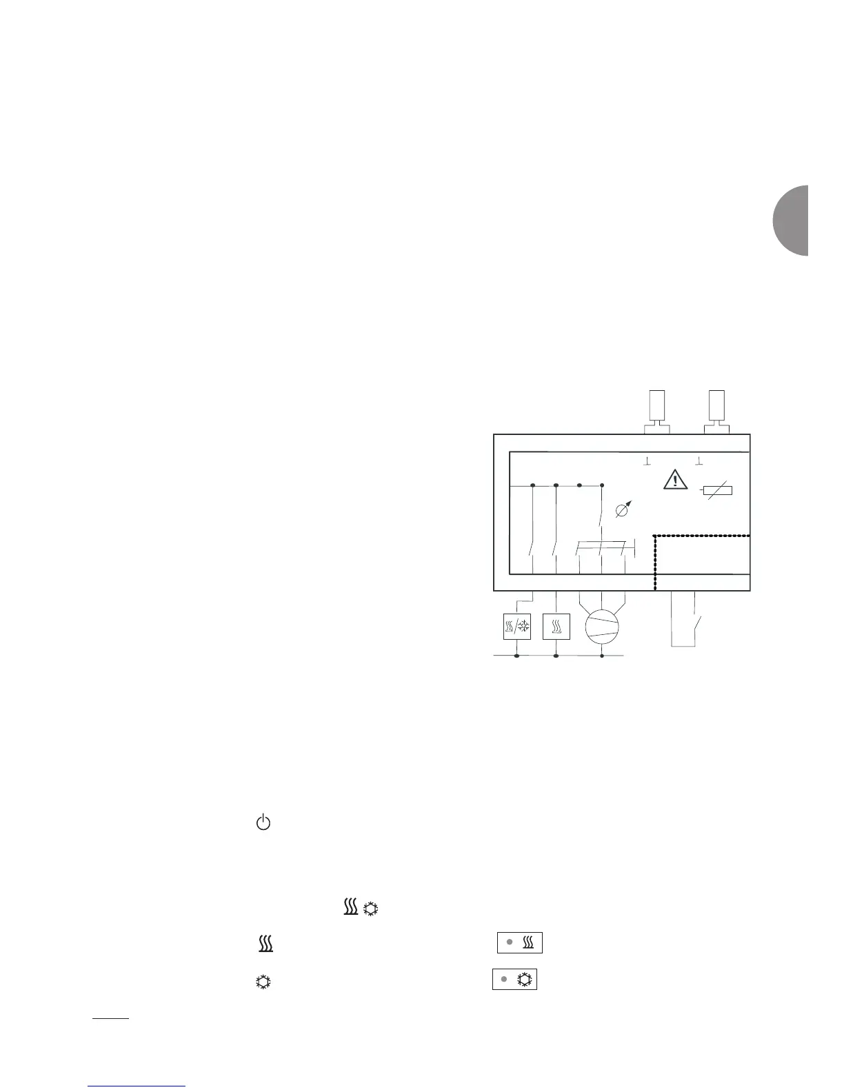
Unit connection diagram:
Technical specifications
n Power supply 230/1/50-60 Hz:
*Maximum current on main power supply: 10A
*Valve: 230V - 1A
*Fan: 230V - 3A cosj 0.9
*Electric heater: 230V - 2000W max
*IP30 protection rating, Class II
n Hot comfort setpoint 19°C
n Cold comfort setpoint 23 or 25°C
n Comfort setpoint settings range: +/- 6K
n Hot economy setpoint -5°K
n Cold economy setpoint +5°K
n Hysteresis: 0.5°K
n Post-ventilation 2 mins
LED operation
n LED for active mode
*LED on in Comfort mode
*LED off in Economy or Frost protection mode
*Flashes if the room temperature <8°C
n LED for heating mode and cooling
*The heating LED
comes on when heating is activated
*The cooling LED
comes on when cooling is activated
Alarm
n The 3 LEDS flash: Fault in the air temperature sensors (indoor environment or return).
N
7
6
543
13
14
L
N
III III
V30
DI1
SELV
Xs
2pt
NTC10000
9
230 V
NTC C/O
1110
GND
8
230 V
50/60 Hz
2
1